Sensit 2 - AMS
Sensit 2 - AMS
Sensit 2 - AMS

Create successful ePaper yourself
Turn your PDF publications into a flip-book with our unique Google optimized e-Paper software.
<strong>AMS</strong> SENSIT II GLASS FRONT VENDOR<br />
L0071, Rev. M<br />
3.0 VENDOR SYSTEMS AND COMPONENTS<br />
3.1 SENSIT II SYSTEM THEORY OF OPERATION<br />
1. The <strong>Sensit</strong> II system is comprised of three elements; the<br />
emitter, the detector, and the control logic. The emitter<br />
is a circuit board with infra-red emitting LED’s located on<br />
one side of the hopper. On the opposite side of the<br />
hopper is a circuit board with infra-red detectors that<br />
measure the intensity of the light. The emitter, the<br />
detector and the control board controls the performance<br />
of the vending operation.<br />
2. When a selection is made, the vend motor will begin to<br />
run. After several seconds, if no product falls in the<br />
hopper, the motor will be stopped, the credit will be<br />
maintained and the customer will be directed to<br />
“PLEASE MAKE ANOTHER SELECTION.”<br />
3. When the controller measures a variation in the light<br />
intensity during the vend cycle, it recognizes that a<br />
product has fallen through the light into the hopper. The<br />
controller stops the vend motor and removes the credit.<br />
4. When the vendor is serviced with the door open, the<br />
protective lens on the detector can become fogged up,<br />
particularly in hot or humid locations. In these cases, the<br />
vendor will display “SENSIT BLOCKED – UNABLE TO<br />
VEND” until the fogging has cleared, usually within a<br />
minute after closing the door.<br />
3.3 VEND SENSOR<br />
3.3.1 Emitter<br />
The emitter, inside a protective housing, is located<br />
on the right side of the hopper when viewing the back of the<br />
door. The emitter sends a beam of infra-red light across<br />
the top of the hopper to the detector.<br />
3.3.2 Detector<br />
The detector is located on the left of the hopper<br />
when viewing the back of the door. The detector, inside a<br />
protective housing, receives the beam of light from the<br />
emitter and sends a signal to the control board based on<br />
the intensity of the beam. When a product drops through<br />
the beam, it causes a change in intensity which is<br />
interpreted by the control as a successful vend. When<br />
servicing the detector board, be mindful of the seven black<br />
detector cells along the top of the board. These can be<br />
knocked out of alignment or damaged by rough handling.<br />
3.4 DOOR<br />
3.4.1 Changer Location<br />
Three screws are installed in the door below the coin<br />
chute. These screws mate to the keyhole slots on the back<br />
of the changer. Refer to Section 4.2.4 Mounting And<br />
Connecting Coin Mechanism.<br />
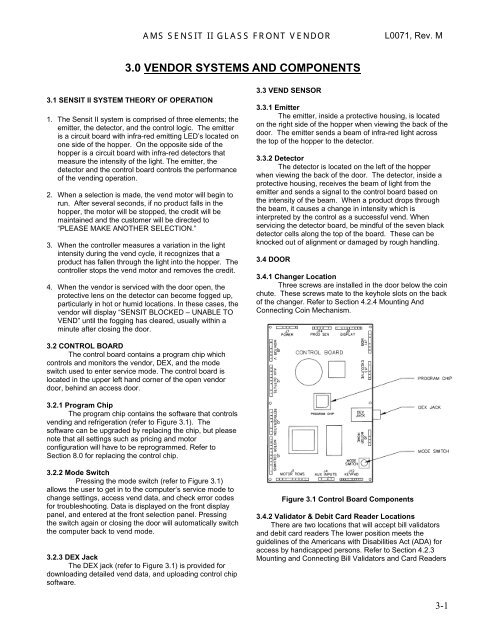
3.2 CONTROL BOARD<br />
The control board contains a program chip which<br />
controls and monitors the vendor, DEX, and the mode<br />
switch used to enter service mode. The control board is<br />
located in the upper left hand corner of the open vendor<br />
door, behind an access door.<br />
3.2.1 Program Chip<br />
The program chip contains the software that controls<br />
vending and refrigeration (refer to Figure 3.1). The<br />
software can be upgraded by replacing the chip, but please<br />
note that all settings such as pricing and motor<br />
configuration will have to be reprogrammed. Refer to<br />
Section 8.0 for replacing the control chip.<br />
3.2.2 Mode Switch<br />
Pressing the mode switch (refer to Figure 3.1)<br />
allows the user to get in to the computer’s service mode to<br />
change settings, access vend data, and check error codes<br />
for troubleshooting. Data is displayed on the front display<br />
panel, and entered at the front selection panel. Pressing<br />
the switch again or closing the door will automatically switch<br />
the computer back to vend mode.<br />
3.2.3 DEX Jack<br />
The DEX jack (refer to Figure 3.1) is provided for<br />
downloading detailed vend data, and uploading control chip<br />
software.<br />
Figure 3.1 Control Board Components<br />
3.4.2 Validator & Debit Card Reader Locations<br />
There are two locations that will accept bill validators<br />
and debit card readers The lower position meets the<br />
guidelines of the Americans with Disabilities Act (ADA) for<br />
access by handicapped persons. Refer to Section 4.2.3<br />
Mounting and Connecting Bill Validators and Card Readers<br />
3-1