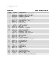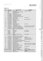
Sensit 2 - AMS
Sensit 2 - AMS
Sensit 2 - AMS

You also want an ePaper? Increase the reach of your titles
YUMPU automatically turns print PDFs into web optimized ePapers that Google loves.
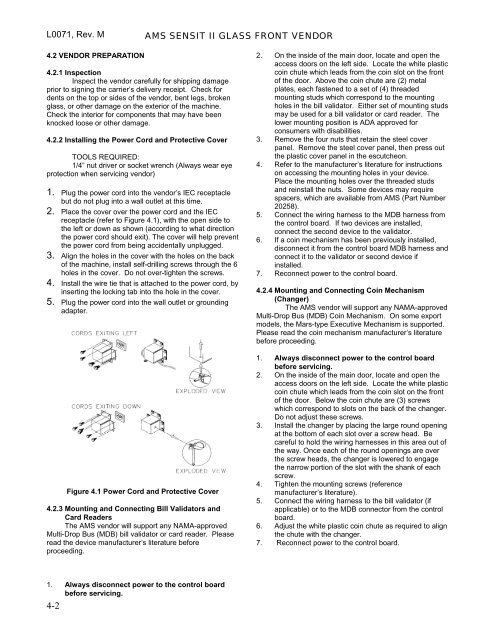
L0071, Rev. M <strong>AMS</strong> SENSIT II GLASS FRONT VENDOR<br />
4.2 VENDOR PREPARATION<br />
4.2.1 Inspection<br />
Inspect the vendor carefully for shipping damage<br />
prior to signing the carrier’s delivery receipt. Check for<br />
dents on the top or sides of the vendor, bent legs, broken<br />
glass, or other damage on the exterior of the machine.<br />
Check the interior for components that may have been<br />
knocked loose or other damage.<br />
4.2.2 Installing the Power Cord and Protective Cover<br />
TOOLS REQUIRED:<br />
1/4” nut driver or socket wrench (Always wear eye<br />
protection when servicing vendor)<br />
1. Plug the power cord into the vendor’s IEC receptacle<br />
but do not plug into a wall outlet at this time.<br />
2. Place the cover over the power cord and the IEC<br />
receptacle (refer to Figure 4.1), with the open side to<br />
the left or down as shown (according to what direction<br />
the power cord should exit). The cover will help prevent<br />
the power cord from being accidentally unplugged.<br />
3. Align the holes in the cover with the holes on the back<br />
of the machine, install self-drilling screws through the 6<br />
holes in the cover. Do not over-tighten the screws.<br />
4. Install the wire tie that is attached to the power cord, by<br />
inserting the locking tab into the hole in the cover.<br />
5. Plug the power cord into the wall outlet or grounding<br />
adapter.<br />
Figure 4.1 Power Cord and Protective Cover<br />
4.2.3 Mounting and Connecting Bill Validators and<br />
Card Readers<br />
The <strong>AMS</strong> vendor will support any NAMA-approved<br />
Multi-Drop Bus (MDB) bill validator or card reader. Please<br />
read the device manufacturer’s literature before<br />
proceeding.<br />
2. On the inside of the main door, locate and open the<br />
access doors on the left side. Locate the white plastic<br />
coin chute which leads from the coin slot on the front<br />
of the door. Above the coin chute are (2) metal<br />
plates, each fastened to a set of (4) threaded<br />
mounting studs which correspond to the mounting<br />
holes in the bill validator. Either set of mounting studs<br />
may be used for a bill validator or card reader. The<br />
lower mounting position is ADA approved for<br />
consumers with disabilities.<br />
3. Remove the four nuts that retain the steel cover<br />
panel. Remove the steel cover panel, then press out<br />
the plastic cover panel in the escutcheon.<br />
4. Refer to the manufacturer’s literature for instructions<br />
on accessing the mounting holes in your device.<br />
Place the mounting holes over the threaded studs<br />
and reinstall the nuts. Some devices may require<br />
spacers, which are available from <strong>AMS</strong> (Part Number<br />
20258).<br />
5. Connect the wiring harness to the MDB harness from<br />
the control board. If two devices are installed,<br />
connect the second device to the validator.<br />
6. If a coin mechanism has been previously installed,<br />
disconnect it from the control board MDB harness and<br />
connect it to the validator or second device if<br />
installed.<br />
7. Reconnect power to the control board.<br />
4.2.4 Mounting and Connecting Coin Mechanism<br />
(Changer)<br />
The <strong>AMS</strong> vendor will support any NAMA-approved<br />
Multi-Drop Bus (MDB) Coin Mechanism. On some export<br />
models, the Mars-type Executive Mechanism is supported.<br />
Please read the coin mechanism manufacturer’s literature<br />
before proceeding.<br />
1. Always disconnect power to the control board<br />
before servicing.<br />
2. On the inside of the main door, locate and open the<br />
access doors on the left side. Locate the white plastic<br />
coin chute which leads from the coin slot on the front<br />
of the door. Below the coin chute are (3) screws<br />
which correspond to slots on the back of the changer.<br />
Do not adjust these screws.<br />
3. Install the changer by placing the large round opening<br />
at the bottom of each slot over a screw head. Be<br />
careful to hold the wiring harnesses in this area out of<br />
the way. Once each of the round openings are over<br />
the screw heads, the changer is lowered to engage<br />
the narrow portion of the slot with the shank of each<br />
screw.<br />
4. Tighten the mounting screws (reference<br />
manufacturer’s literature).<br />
5. Connect the wiring harness to the bill validator (if<br />
applicable) or to the MDB connector from the control<br />
board.<br />
6. Adjust the white plastic coin chute as required to align<br />
the chute with the changer.<br />
7. Reconnect power to the control board.<br />
1. Always disconnect power to the control board<br />
before servicing.<br />
4-2