Elektronika 2010-11.pdf - Instytut Systemów Elektronicznych ...
Elektronika 2010-11.pdf - Instytut Systemów Elektronicznych ...
Elektronika 2010-11.pdf - Instytut Systemów Elektronicznych ...
Create successful ePaper yourself
Turn your PDF publications into a flip-book with our unique Google optimized e-Paper software.
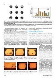
Fig. 4. Portable real-time PCR DNA analyzer: a) LOC on author’s<br />
finger, b) view of the docking station ready to work<br />
Rys. 4. Przenośny analizator DNA PCR czasu rzeczywistego:<br />
a) mikrosystem typu lab-on-chip w porównaniu do monety<br />
10-centowej, b) widok stacji dokującej gotowej do pracy<br />
a)<br />
Fluorescence intensity [au]<br />
a)<br />
b)<br />
b)<br />
100<br />
Normalized fluorescence intensity<br />
[au]<br />
80<br />
60<br />
40<br />
20<br />
0<br />
100 140 180 220 260 300 340 380 420<br />
Time [s]<br />
0,6<br />
0,5<br />
0,4<br />
0,3<br />
0,2<br />
0,1<br />
0<br />
Fluorescence signal<br />
Temperature profile<br />
1 2 3 4 5 6 7 8 9 10 11 12 13 14 15 16 17 18 19 20 21 22 23 24 25 26 27 28 29 30 31 32 33 34<br />
PCR cycle<br />
Fig. 5. Real-time PCR of Campylobacter j. DNA: a) fluorescence<br />
intensity change following PCR temperature profiling, b) S-curve<br />
– like bar graph describing kinetics of DNA amplification<br />
Rys. 5. PCR czasu rzeczywistego DNA bakterii Campylobacter j.:<br />
a) zmiany intensywności fluorescencji w czasie cykli temperaturowych<br />
reakcji PCR, b) krzywa typu S opisująca kinetykę namnażania<br />
materiału genetycznego<br />
cialized PCR temperature controller connected to the computer.<br />
The holder with ready to use LOC is positioned in the<br />
docking station (15 × 5 × 7 cm 3 ) in the way ensuring laser light<br />
introduction into PCR microchamber and fluorescence light<br />
collection [10]. Than, PCR temperature profiling and fluorescence<br />
signal acquisition are started. The laser light does not<br />
illuminate whole PCR microchamber but it does only in part<br />
of the chamber which corresponds to a laser light distribution<br />
cone. Therefore, the fluorescence is induced and emitted from<br />
a volume in picoliter range.<br />
View of the chip and hand-held docking station with positioned<br />
chip holder just before start of the PCR process<br />
is shown on Fig. 4.<br />
The pre-validation tests of LOC – based system for detection<br />
of Campylobacter j. were carried out with 48 chicken<br />
fecal samples [9]. All the steps – from sample preparation to<br />
final result – were performed in the single chip with 2,5 μl volume<br />
of reagents. The ratio of PCR efficiencies between onchip<br />
and on-tube (reference) was up to 300%. The sensitivity<br />
of on-chip PCR was determined as 0,7–7 ng/ml of template<br />
DNA – similar result were obtained for on-tube amplification.<br />
The LOC real-time PCR process took 30 min – at least 4 times<br />
shorter than PCR on-tube.<br />
An example of the fluorescence intensity change following<br />
temperature profiling during PCR process is shown on Fig. 5a.<br />
S-curve graph of the real-time PCR process has been compiled<br />
on the base of average fluorescence intensity during<br />
extension step of each PCR cycle (Fig. 5b). Obtained S-curve<br />
is comparable to the characteristic achieved by the use of the<br />
chip observed under epifluorescence microscope equipped<br />
with PMT.<br />
Carried out pre-validation tests confirmed usefulness<br />
of the developed optical instrumentation, as well as the whole<br />
LOC-based system for real-time PCR detection of Campylobacter<br />
j.<br />
Summary and conclusions<br />
Presented here idea and technical realization of novel fluorescence<br />
readout has been successfully tested and applied<br />
in various LOC-based instrumentation. The main advantage<br />
of presented here solution is a ratio of the price of optical readout<br />
components to the sensitivity of the whole unit. It has been<br />
obtained by application of low-cost components and “intelligent”<br />
software for conditioning of collected data. As the result, sensitivity<br />
of the novel system is comparable to sophisticated “large<br />
scale” solutions with 100-times lower consumables costs. The<br />
novel image sensor – based fluorescence detection enables development<br />
of point-of-care devices with advanced fluorescence<br />
detection with sensitivity level comparable to standard laboratory<br />
equipment. Currently, there are works on further development of<br />
the CCD image sensor – based fluorescence detection method<br />
and instrumentation toward multiwavelength detection. Preliminary<br />
works indicated also that developed optical instrumentation<br />
can be successfully used also in portable cocaine detector<br />
for monitoring of professional driver’s cocaine abuse [11],<br />
in LOC-based gel electrophoresis DNA analyzer or microcytometer<br />
for optical characterization of bio- samples [12].<br />
The works were/are financed by 6. FP OPTOLABCARD, 7 FP.<br />
LABONFOIL and Statutory Grants of PWr. Author would like<br />
to thank to J. Dziuban, A. Górecka-Drzazga, P. Knapkiewicz,<br />
P. Szczepańska and W. Kubicki from Wrocław University of Technology,<br />
J. Koszur and B. Latecki from Institute of Electron Technology<br />
in Warsaw, D. D. Bang from Danish Technical University and J.<br />
M. Ruano-Lopez from Ikerlan in Spain for fruitful co-operation.<br />
<strong>Elektronika</strong> 11/<strong>2010</strong> 35


