GRAIN DRYER & PARTS BOOK - Opico
GRAIN DRYER & PARTS BOOK - Opico
GRAIN DRYER & PARTS BOOK - Opico

Create successful ePaper yourself
Turn your PDF publications into a flip-book with our unique Google optimized e-Paper software.
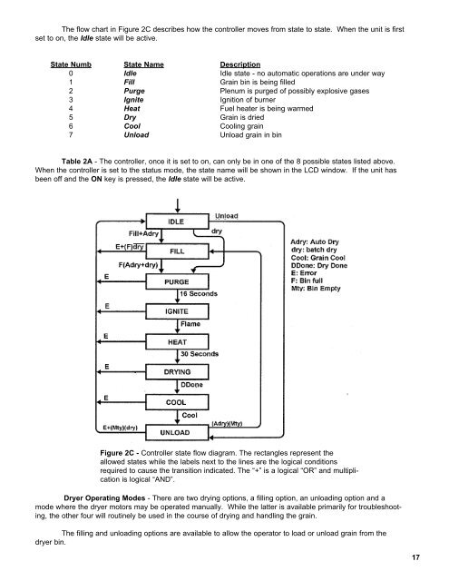
The flow chart in Figure 2C describes how the controller moves from state to state. When the unit is first<br />
set to on, the Idle state will be active.<br />
State Numb State Name Description<br />
0 Idle Idle state - no automatic operations are under way<br />
1 Fill Grain bin is being filled<br />
2 Purge Plenum is purged of possibly explosive gases<br />
3 Ignite Ignition of burner<br />
4 Heat Fuel heater is being warmed<br />
5 Dry Grain is dried<br />
6 Cool Cooling grain<br />
7 Unload Unload grain in bin<br />
Table 2A - The controller, once it is set to on, can only be in one of the 8 possible states listed above.<br />
When the controller is set to the status mode, the state name will be shown in the LCD window. If the unit has<br />
been off and the ON key is pressed, the Idle state will be active.<br />
Figure 2C - Controller state flow diagram. The rectangles represent the<br />
allowed states while the labels next to the lines are the logical conditions<br />
required to cause the transition indicated. The “+” is a logical “OR” and multiplication<br />
is logical “AND”.<br />
Dryer Operating Modes - There are two drying options, a filling option, an unloading option and a<br />
mode where the dryer motors may be operated manually. While the latter is available primarily for troubleshooting,<br />
the other four will routinely be used in the course of drying and handling the grain.<br />
The filling and unloading options are available to allow the operator to load or unload grain from the<br />
dryer bin.<br />
17