

4-CYCLE OVERHEAD VALVE ENGINES - Small Engine Discount
4-CYCLE OVERHEAD VALVE ENGINES - Small Engine Discount
4-CYCLE OVERHEAD VALVE ENGINES - Small Engine Discount

You also want an ePaper? Increase the reach of your titles
YUMPU automatically turns print PDFs into web optimized ePapers that Google loves.
3 AMP DC ALTERNATOR SYSTEM -<br />
DIODE IN HARNESS SLEEVE<br />
This system has a diode included in the red wire which<br />
converts the alternating current (A.C.) to direct current.<br />
The direct current (D.C.) is used to provide a trickle<br />
charge for the battery. The leads from the alternator<br />
and the type of connector may vary, but the output<br />
readings will be the same.<br />
CHECKING THE SYSTEM: Remove the fuse from<br />
fuse holder and check the fuse to make certain it is<br />
good. If faulty, replace with a six (6) AMP fuse.<br />
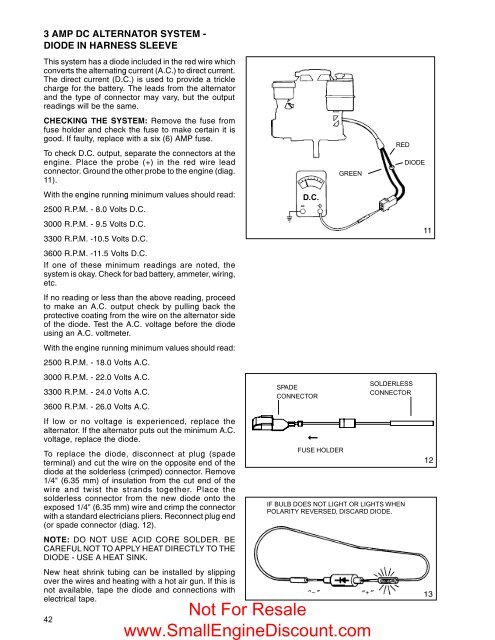
To check D.C. output, separate the connectors at the<br />
engine. Place the probe (+) in the red wire lead<br />
connector. Ground the other probe to the engine (diag.<br />
11).<br />
With the engine running minimum values should read:<br />
2500 R.P.M. - 8.0 Volts D.C.<br />
3000 R.P.M. - 9.5 Volts D.C.<br />
3300 R.P.M. -10.5 Volts D.C.<br />
3600 R.P.M. -11.5 Volts D.C.<br />
If one of these minimum readings are noted, the<br />
system is okay. Check for bad battery, ammeter, wiring,<br />
etc.<br />
If no reading or less than the above reading, proceed<br />
to make an A.C. output check by pulling back the<br />
protective coating from the wire on the alternator side<br />
of the diode. Test the A.C. voltage before the diode<br />
using an A.C. voltmeter.<br />
With the engine running minimum values should read:<br />
2500 R.P.M. - 18.0 Volts A.C.<br />
3000 R.P.M. - 22.0 Volts A.C.<br />
3300 R.P.M. - 24.0 Volts A.C.<br />
3600 R.P.M. - 26.0 Volts A.C.<br />
If low or no voltage is experienced, replace the<br />
alternator. If the alternator puts out the minimum A.C.<br />
voltage, replace the diode.<br />
To replace the diode, disconnect at plug (spade<br />
terminal) and cut the wire on the opposite end of the<br />
diode at the solderless (crimped) connector. Remove<br />
1/4" (6.35 mm) of insulation from the cut end of the<br />
wire and twist the strands together. Place the<br />
solderless connector from the new diode onto the<br />
exposed 1/4" (6.35 mm) wire and crimp the connector<br />
with a standard electricians pliers. Reconnect plug end<br />
(or spade connector (diag. 12).<br />
NOTE: DO NOT USE ACID CORE SOLDER. BE<br />
CAREFUL NOT TO APPLY HEAT DIRECTLY TO THE<br />
DIODE - USE A HEAT SINK.<br />
New heat shrink tubing can be installed by slipping<br />
over the wires and heating with a hot air gun. If this is<br />
not available, tape the diode and connections with<br />
electrical tape.<br />
42<br />
D.C.<br />
SPADE<br />
CONNECTOR<br />
FUSE HOLDER<br />
GREEN<br />
RED<br />
IF BULB DOES NOT LIGHT OR LIGHTS WHEN<br />
POLARITY REVERSED, DISCARD DIODE.<br />
Not For Resale<br />
www.<strong>Small</strong><strong>Engine</strong><strong>Discount</strong>.com<br />
Þ<br />
SOLDERLESS<br />
CONNECTOR<br />
DIODE<br />
11<br />
12<br />
13


