

4-CYCLE OVERHEAD VALVE ENGINES - Small Engine Discount
4-CYCLE OVERHEAD VALVE ENGINES - Small Engine Discount
4-CYCLE OVERHEAD VALVE ENGINES - Small Engine Discount

You also want an ePaper? Increase the reach of your titles
YUMPU automatically turns print PDFs into web optimized ePapers that Google loves.
BRAKE BRACKET ASSEMBLY<br />
Late production brake brackets are serviceable only by installing a complete brake bracket assembly.<br />
On serviceable brake brackets, continue by removing the alignment tool. Release the spring tension by unhooking<br />
the short end of the spring from bracket with a pliers. Remove the “E” clip from the brake pad shaft. Slide the pad<br />
lever from the shaft and unhook the link. Inspect the brake pad for dirt, oil or grease contamination. If the pad is<br />
contaminated, or if there is less than .060" (1.524 mm) thickness of brake pad material at the pad's thinnest point,<br />
replacement is necessary. The brake pad is bonded to the brake lever and must be replaced as an assembly.<br />
Rehook the link, install the brake lever and pad assembly, install the "E" clip, rehook the short end of the spring<br />
and continue to reassemble the brake system in the reverse order of disassembly.<br />
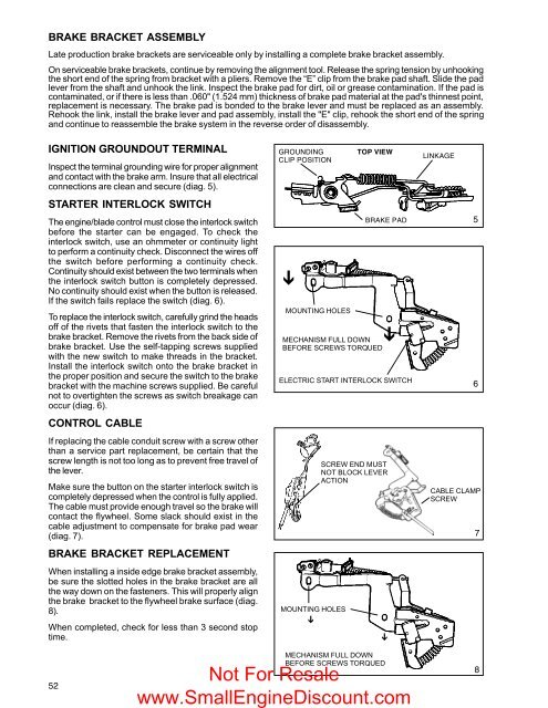
IGNITION GROUNDOUT TERMINAL<br />
Inspect the terminal grounding wire for proper alignment<br />
and contact with the brake arm. Insure that all electrical<br />
connections are clean and secure (diag. 5).<br />
STARTER INTERLOCK SWITCH<br />
The engine/blade control must close the interlock switch<br />
before the starter can be engaged. To check the<br />
interlock switch, use an ohmmeter or continuity light<br />
to perform a continuity check. Disconnect the wires off<br />
the switch before performing a continuity check.<br />
Continuity should exist between the two terminals when<br />
the interlock switch button is completely depressed.<br />
No continuity should exist when the button is released.<br />
If the switch fails replace the switch (diag. 6).<br />
To replace the interlock switch, carefully grind the heads<br />
off of the rivets that fasten the interlock switch to the<br />
brake bracket. Remove the rivets from the back side of<br />
brake bracket. Use the self-tapping screws supplied<br />
with the new switch to make threads in the bracket.<br />
Install the interlock switch onto the brake bracket in<br />
the proper position and secure the switch to the brake<br />
bracket with the machine screws supplied. Be careful<br />
not to overtighten the screws as switch breakage can<br />
occur (diag. 6).<br />
CONTROL CABLE<br />
If replacing the cable conduit screw with a screw other<br />
than a service part replacement, be certain that the<br />
screw length is not too long as to prevent free travel of<br />
the lever.<br />
Make sure the button on the starter interlock switch is<br />
completely depressed when the control is fully applied.<br />
The cable must provide enough travel so the brake will<br />
contact the flywheel. Some slack should exist in the<br />
cable adjustment to compensate for brake pad wear<br />
(diag. 7).<br />
BRAKE BRACKET REPLACEMENT<br />
When installing a inside edge brake bracket assembly,<br />
be sure the slotted holes in the brake bracket are all<br />
the way down on the fasteners. This will properly align<br />
the brake bracket to the flywheel brake surface (diag.<br />
8).<br />
When completed, check for less than 3 second stop<br />
time.<br />
GROUNDING<br />
CLIP POSITION<br />
Ô<br />
MOUNTING HOLES<br />
MOUNTING HOLES<br />
Ô<br />
TOP VIEW<br />
MECHANISM FULL DOWN<br />
BEFORE SCREWS TORQUED<br />
BRAKE PAD<br />
Ô<br />
ELECTRIC START INTERLOCK SWITCH<br />
SCREW END MUST<br />
NOT BLOCK LEVER<br />
ACTION<br />
Ô<br />
LINKAGE<br />
5<br />
6<br />
CABLE CLAMP<br />
SCREW<br />
7<br />
52<br />
MECHANISM FULL DOWN<br />
BEFORE SCREWS TORQUED<br />
Not For Resale<br />
www.<strong>Small</strong><strong>Engine</strong><strong>Discount</strong>.com<br />
8


