

4-CYCLE OVERHEAD VALVE ENGINES - Small Engine Discount
4-CYCLE OVERHEAD VALVE ENGINES - Small Engine Discount
4-CYCLE OVERHEAD VALVE ENGINES - Small Engine Discount

You also want an ePaper? Increase the reach of your titles
YUMPU automatically turns print PDFs into web optimized ePapers that Google loves.
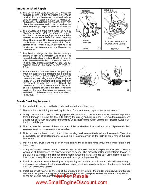
Inspection And Repair<br />
1. The pinion gear parts should be checked for<br />
damage or wear. If the gear does not engage<br />
or slips, it should be washed in solvent (rubber<br />
parts cleaned in soap and water) to remove dirt<br />
and grease, and dried before reassembly. Also<br />
check the armature and drive nut splines for<br />
wear or damage. Replace parts as necessary.<br />
2. The brushes and brush card holder should be<br />
checked for wear. With the armature in place<br />
and the brushes engaging the commutator<br />
surface, check the brushes for wear. Brushes<br />
should be replaced if the brush wire approaches<br />
the bottom of the brush holder slot. Brush<br />
springs must exhibit enough strength to keep<br />
tension on the brushes and hold them on the<br />
commutator.<br />
3. The field windings can be checked using a<br />
continuity light or ohmmeter. Attach one lead<br />
to each field coil connection. Continuity should<br />
exist between each field coil connection, and<br />
no continuity should exist between the field coil<br />
connections and the starter housing (diag. 32<br />
& 33).<br />
4. The armature should be checked for glazing or<br />
wear. If necessary the armature can be turned<br />
down in a lathe. While rotating, polish the<br />
commutator bars using a piece of 00 sandpaper<br />
(diag. 34). Light pressure and back and forth<br />
movement should be used. Recut the<br />
commutator bars to a depth equal to the width<br />
of the insulators between the bars. Check for<br />
continuity between the copper commutator bars<br />
and the iron of the armature, none should exist<br />
(diag. 35).<br />
FIELD COIL<br />
CONNECTORS<br />
BRUSH<br />
SPRINGS<br />
FIELD COIL<br />
CONNECTORS<br />
CONNECTION POINT OF<br />
POWER CORD LEADS<br />
12 VOLT 32<br />
120 VOLT<br />
33<br />
34 35<br />
Brush Card Replacement<br />
1. Loosen but do not remove the two nuts on the starter terminal post.<br />
2. Remove the nuts holding the end cap in place. Remove the end cap and the thrust washer.<br />
3. Grasp the thru bolts using a vise grip positioned as close to the flanged end as possible to prevent<br />
thread damage. Remove the two nuts holding the driving end cap in place. Remove the armature and<br />
driving cap assembly, followed by the two thru bolts. Notice the position of the brush ground eyelet under<br />
the thru bolt flange.<br />
4. Note or mark the position of the connectors of the brush wires. Use a wire cutter to clip the solid field<br />
wires as close to the connectors as possible.<br />
5. Note or mark the brush card in the starter housing, and remove the brush card assembly. Clean the<br />
accumulated dirt off all starter parts. Scrape the insulating varnish off the last 1/2" (12.7 mm) of the solid<br />
field wires.<br />
6. Insert the new brush card into position while guiding the solid field wires through the proper slots in the<br />
brush card.<br />
7. Crimp and solder the brush leads to the solid field wires. Use a needle nose pliers or vise grip to hold the<br />
woven brush lead close to the connector while soldering. This prevents solder and heat from flowing up<br />
the brush lead. Insulate the crimped connection nearest the starter terminal post using electrical tape or<br />
heat shrink tubing. Route the wires to prevent damage during assembly.<br />
8. Install the armature into the housing while spreading the brushes. Install the thru bolts while checking to<br />
make sure the bolts go thru the ground brush eyelet terminals. Install and tighten the drive end thru bolt<br />
nuts, but do not overtighten.<br />
9. Install the thrust washer on the end of the armature and the install the starter end cap. Secure the cap<br />
with the locking nuts and tighten the nut on the starter terminal post. Rotate the armature by hand to<br />
check for binding before installation on the engine.<br />
Not For Resale<br />
www.<strong>Small</strong><strong>Engine</strong><strong>Discount</strong>.com<br />
49


