Design Methodologies of LTCC Bandpass Filters, Diplexer, and ...
Design Methodologies of LTCC Bandpass Filters, Diplexer, and ...
Design Methodologies of LTCC Bandpass Filters, Diplexer, and ...

Create successful ePaper yourself
Turn your PDF publications into a flip-book with our unique Google optimized e-Paper software.
TANG AND YOU: DESIGN METHODOLOGIES OF <strong>LTCC</strong> BANDPASS FILTERS, DIPLEXER, AND TRIPLEXER WITH TRANSMISSION ZEROS 719<br />
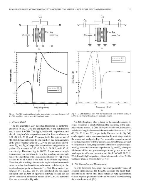
Fig. 6. 2.4-GHz b<strong>and</strong>pass filter with the transmission zero at the frequency <strong>of</strong><br />
1.9 GHz. (a) Filter architecture. (b) Simulated results.<br />
A. Circuit Model<br />
The first example is a 2.4-GHz b<strong>and</strong>pass filter. Its center frequency<br />
is set at 2.4 GHz <strong>and</strong> the frequency <strong>of</strong> the transmission<br />
zero is set at 1.9 GHz. The ripple, b<strong>and</strong>width, impedance, <strong>and</strong><br />
electric length <strong>of</strong> the coupled transmission line are chosen as<br />
0.01 dB, 6%, 30 , <strong>and</strong> 12 , respectively. By making use <strong>of</strong><br />
(1)–(17) derived in Section II, one can show that the parameters<br />
<strong>of</strong> the cross-coupled capacitor , even- <strong>and</strong> odd-mode impedances<br />
<strong>and</strong> <strong>of</strong> the parallel-coupled line, <strong>and</strong> grounded capacitors<br />
are equal to 3.93 pF, 39.24 , 24.28 , <strong>and</strong> 6.47 pF,<br />
respectively. Therefore, is 0.0206. A quarter-wavelength<br />
transmission line is utilized to form the matching circuit, <strong>and</strong>,<br />
hence, the impedance <strong>of</strong> this transmission line is 48.47 , which<br />
is close to 50 , which is the vale <strong>of</strong> the system impedance.<br />
Therefore, the matching circuit can be neglected <strong>and</strong> the secondorder<br />
combline b<strong>and</strong>pass filter can be connected directly to the<br />
input <strong>and</strong> output ports, as shown in Fig. 6(a). These derived parameters<br />
<strong>and</strong> are substituted into the circuit<br />
simulator such as ADS or equivalent s<strong>of</strong>tware to carry out the<br />
circuit simulation. Simulation results <strong>of</strong> the 2.4-GHz b<strong>and</strong>pass<br />
filter are presented in Fig. 6(b).<br />
Fig. 7. 2-GHz b<strong>and</strong>pass filter with the transmission zero at the frequency <strong>of</strong><br />
2.5 GHz. (a) Filter architecture. (b) Simulated results.<br />
A 2-GHz b<strong>and</strong>pass filter is taken as the second example. Its<br />
center frequency is set at 2 GHz <strong>and</strong> the frequency <strong>of</strong> the transmission<br />
zero is set at 2.5 GHz. The ripple, b<strong>and</strong>width, impedance,<br />
<strong>and</strong> electric length <strong>of</strong> the coupled transmission line are set as 0.01<br />
dB, 7%, 30 , <strong>and</strong> 30 , respectively. The structure in Fig. 5(b)<br />
can be applied to the transformation for the matching circuit in<br />
the source <strong>and</strong> load ports. Fig. 7(a) shows the equivalent circuit<br />
<strong>of</strong> the b<strong>and</strong>pass filter with the transmission zero at the higher skirt<br />
<strong>of</strong> the passb<strong>and</strong>. Here, the parameters <strong>of</strong> the cross-coupled capacitor<br />
, even- <strong>and</strong> odd-mode impedances <strong>and</strong> <strong>of</strong> the parallel-coupled<br />
line, the grounded capacitors , <strong>and</strong> source <strong>and</strong><br />
load capacitors are calculated as 1.26 pF, 54.96 , 20.63 ,<br />
2.54 pF, <strong>and</strong> 0.8 pF, respectively. Simulation results <strong>of</strong> this 2-GHz<br />
b<strong>and</strong>pass filter are presented in Fig. 7(b).<br />
B. EM Simulation <strong>and</strong> Measurement<br />
Prior to designing the circuit, the exact parameter values <strong>of</strong><br />
ceramic sheets such as the dielectric constant <strong>and</strong> layer thickness<br />
should be known first. These values are very significant to<br />
extract physical parameters <strong>and</strong> can be critical in constructing<br />
the equivalent circuit [21].