Design Methodologies of LTCC Bandpass Filters, Diplexer, and ...
Design Methodologies of LTCC Bandpass Filters, Diplexer, and ...
Design Methodologies of LTCC Bandpass Filters, Diplexer, and ...

You also want an ePaper? Increase the reach of your titles
YUMPU automatically turns print PDFs into web optimized ePapers that Google loves.
TANG AND YOU: DESIGN METHODOLOGIES OF <strong>LTCC</strong> BANDPASS FILTERS, DIPLEXER, AND TRIPLEXER WITH TRANSMISSION ZEROS 721<br />
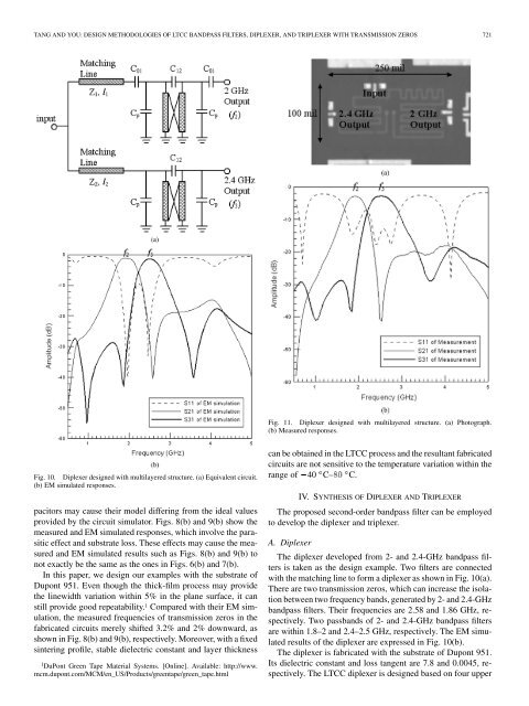
Fig. 11. <strong>Diplexer</strong> designed with multilayered structure. (a) Photograph.<br />
(b) Measured responses.<br />
Fig. 10. <strong>Diplexer</strong> designed with multilayered structure. (a) Equivalent circuit.<br />
(b) EM simulated responses.<br />
pacitors may cause their model differing from the ideal values<br />
provided by the circuit simulator. Figs. 8(b) <strong>and</strong> 9(b) show the<br />
measured <strong>and</strong> EM simulated responses, which involve the parasitic<br />
effect <strong>and</strong> substrate loss. These effects may cause the measured<br />
<strong>and</strong> EM simulated results such as Figs. 8(b) <strong>and</strong> 9(b) to<br />
not exactly be the same as the ones in Figs. 6(b) <strong>and</strong> 7(b).<br />
In this paper, we design our examples with the substrate <strong>of</strong><br />
Dupont 951. Even though the thick-film process may provide<br />
the linewidth variation within 5% in the plane surface, it can<br />
still provide good repeatability. 1 Compared with their EM simulation,<br />
the measured frequencies <strong>of</strong> transmission zeros in the<br />
fabricated circuits merely shifted 3.2% <strong>and</strong> 2% downward, as<br />
shown in Fig. 8(b) <strong>and</strong> 9(b), respectively. Moreover, with a fixed<br />
sintering pr<strong>of</strong>ile, stable dielectric constant <strong>and</strong> layer thickness<br />
1 DuPont Green Tape Material Systems. [Online]. Available: http://www.<br />
mcm.dupont.com/MCM/en_US/Products/greentape/green_tape.html<br />
can be obtained in the <strong>LTCC</strong> process <strong>and</strong> the resultant fabricated<br />
circuits are not sensitive to the temperature variation within the<br />
range <strong>of</strong> 40 C– C.<br />
IV. SYNTHESIS OF DIPLEXER AND TRIPLEXER<br />
The proposed second-order b<strong>and</strong>pass filter can be employed<br />
to develop the diplexer <strong>and</strong> triplexer.<br />
A. <strong>Diplexer</strong><br />
The diplexer developed from 2- <strong>and</strong> 2.4-GHz b<strong>and</strong>pass filters<br />
is taken as the design example. Two filters are connected<br />
with the matching line to form a diplexer as shown in Fig. 10(a).<br />
There are two transmission zeros, which can increase the isolation<br />
between two frequency b<strong>and</strong>s, generated by 2- <strong>and</strong> 2.4-GHz<br />
b<strong>and</strong>pass filters. Their frequencies are 2.58 <strong>and</strong> 1.86 GHz, respectively.<br />
Two passb<strong>and</strong>s <strong>of</strong> 2- <strong>and</strong> 2.4-GHz b<strong>and</strong>pass filters<br />
are within 1.8–2 <strong>and</strong> 2.4–2.5 GHz, respectively. The EM simulated<br />
results <strong>of</strong> the diplexer are expressed in Fig. 10(b).<br />
The diplexer is fabricated with the substrate <strong>of</strong> Dupont 951.<br />
Its dielectric constant <strong>and</strong> loss tangent are 7.8 <strong>and</strong> 0.0045, respectively.<br />
The <strong>LTCC</strong> diplexer is designed based on four upper