Design Methodologies of LTCC Bandpass Filters, Diplexer, and ...
Design Methodologies of LTCC Bandpass Filters, Diplexer, and ...
Design Methodologies of LTCC Bandpass Filters, Diplexer, and ...

You also want an ePaper? Increase the reach of your titles
YUMPU automatically turns print PDFs into web optimized ePapers that Google loves.
720 IEEE TRANSACTIONS ON MICROWAVE THEORY AND TECHNIQUES, VOL. 54, NO. 2, FEBRUARY 2006<br />
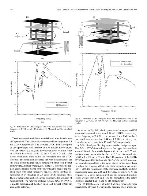
Fig. 8. Fabricated 2.4-GHz b<strong>and</strong>pass filter with transmission zero at the<br />
frequency <strong>of</strong> 1.9 GHz. (a) 3-D structure. (b) Measured <strong>and</strong> EM simulated<br />
results.<br />
Two filters mentioned above are fabricated with the substrate<br />
<strong>of</strong> Dupont 951. Their dielectric constant <strong>and</strong> loss tangent are 7.8<br />
<strong>and</strong> 0.0045, respectively. The 2.4-GHz <strong>LTCC</strong> filter is designed<br />
on one upper layer with the sheet <strong>of</strong> 1.57 mil, six middle layers<br />
with the sheet <strong>of</strong> 3.6 mil, <strong>and</strong> three lower layers with the sheet<br />
<strong>of</strong> 1.57 mil. Its overall size is 110 mil 92 mil 28 mil. After<br />
circuit simulation, these values are converted into the <strong>LTCC</strong><br />
structure. The simulation is carried out with the assistant <strong>of</strong> the<br />
full-wave electromagnetic (EM) simulator Sonnet from Sonnet<br />
S<strong>of</strong>tware Inc., North Syracuse, NY. In the 3-D structure, the parallel-coupled<br />
line is placed on the lower layer to reduce the coupling<br />
effect with other capacitors. Fig. 8(a) shows the three-dimensional<br />
(3-D) structure <strong>of</strong> 2.4-GHz <strong>LTCC</strong> b<strong>and</strong>pass filter.<br />
The on-wafer tester has been chosen to improve the accuracy <strong>of</strong><br />
measurement. The network analyzer Agilent N5230A PNA_L<br />
is used to measure, <strong>and</strong> the short-open-load-through (SOLT) is<br />
adopted to calibrate.<br />
Fig. 9. Fabricated 2-GHz b<strong>and</strong>pass filter with transmission zero at the<br />
frequency <strong>of</strong> 2.5 GHz. (a) 3-D structure. (b) Measured <strong>and</strong> EM simulated<br />
results.<br />
As shown in Fig. 8(b), the frequencies <strong>of</strong> measured <strong>and</strong> EM<br />
simulated transmission zeros are 1.84 <strong>and</strong> 1.9 GHz, respectively.<br />
At the frequency <strong>of</strong> 2.4 GHz, the measured <strong>and</strong> EM simulated<br />
insertion losses are less than 1.44 <strong>and</strong> 1.3 dB, respectively; the<br />
return losses are greater than 15 <strong>and</strong> 17 dB, respectively.<br />
A 2-GHz b<strong>and</strong>pass filter is given as another design example.<br />
This 2-GHz <strong>LTCC</strong> filter is designed on five upper layers with the<br />
sheet <strong>of</strong> 3.6 mil, four middle layers with the sheet <strong>of</strong> 1.57 mil,<br />
<strong>and</strong> two lower layers with the sheet <strong>of</strong> 3.6 mil. Its overall size<br />
is 107 mil 102 mil 32 mil. The 3-D structure <strong>of</strong> the 2-GHz<br />
<strong>LTCC</strong> b<strong>and</strong>pass filter is shown in Fig. 9(a). In the 3-D structure,<br />
the parallel-coupled line is the same placed on the lower layer<br />
to reduce the coupling effect with other capacitors. As shown<br />
in Fig. 9(b), the frequencies <strong>of</strong> the measured <strong>and</strong> EM simulated<br />
transmission zeros are 2.45 <strong>and</strong> 2.5 GHz, respectively. At the<br />
frequency <strong>of</strong> 2 GHz, the measured <strong>and</strong> EM simulated insertion<br />
losses are less than 1.45 <strong>and</strong> 1.26 dB, respectively; the return<br />
losses are greater than 19 <strong>and</strong> 39 dB, respectively.<br />
The <strong>LTCC</strong> technology is a kind <strong>of</strong> thick-film process. In order<br />
to realize the physical 3-D circuit, the parasitic effect among ca-