SC16IS740/750/760 Single UART with I2C-bus/SPI interface, 64 ...
SC16IS740/750/760 Single UART with I2C-bus/SPI interface, 64 ...
SC16IS740/750/760 Single UART with I2C-bus/SPI interface, 64 ...

Create successful ePaper yourself
Turn your PDF publications into a flip-book with our unique Google optimized e-Paper software.
NXP Semiconductors<br />
<strong>SC16IS740</strong>/<strong>750</strong>/<strong>760</strong><br />
<strong>Single</strong> <strong>UART</strong> <strong>with</strong> I 2 C-<strong>bus</strong>/<strong>SPI</strong> <strong>interface</strong>, <strong>64</strong>-byte FIFOs, IrDA SIR<br />
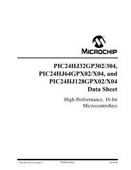
<strong>UART</strong> 1 <strong>UART</strong> 2<br />
RX<br />
FIFO<br />
SERIAL TO<br />
PARALLEL<br />
RX<br />
TX<br />
PARALLEL<br />
TO SERIAL<br />
TX<br />
FIFO<br />
FLOW<br />
CONTROL<br />
RTS<br />
CTS<br />
FLOW<br />
CONTROL<br />
TX<br />
FIFO<br />
PARALLEL<br />
TO SERIAL<br />
TX<br />
RX<br />
SERIAL TO<br />
PARALLEL<br />
RX<br />
FIFO<br />
FLOW<br />
CONTROL<br />
CTS<br />
RTS<br />
FLOW<br />
CONTROL<br />
002aab656<br />
Fig 8.<br />
Autoflow control (auto RTS and auto CTS) example<br />
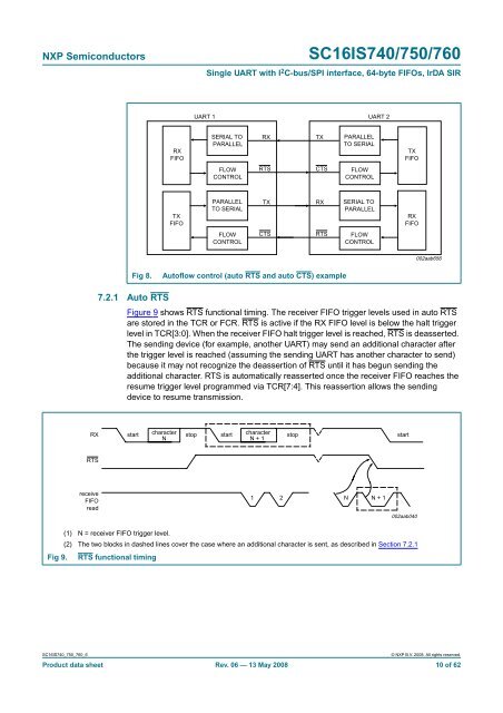
7.2.1 Auto RTS<br />
Figure 9 shows RTS functional timing. The receiver FIFO trigger levels used in auto RTS<br />
are stored in the TCR or FCR. RTS is active if the RX FIFO level is below the halt trigger<br />
level in TCR[3:0]. When the receiver FIFO halt trigger level is reached, RTS is deasserted.<br />
The sending device (for example, another <strong>UART</strong>) may send an additional character after<br />
the trigger level is reached (assuming the sending <strong>UART</strong> has another character to send)<br />
because it may not recognize the deassertion of RTS until it has begun sending the<br />
additional character. RTS is automatically reasserted once the receiver FIFO reaches the<br />
resume trigger level programmed via TCR[7:4]. This reassertion allows the sending<br />
device to resume transmission.<br />
RX<br />
start<br />
character<br />
N<br />
stop<br />
start<br />
character<br />
N + 1<br />
stop<br />
start<br />
RTS<br />
receive<br />
FIFO<br />
read<br />
1 2<br />
N N + 1<br />
002aab040<br />
(1) N = receiver FIFO trigger level.<br />
(2) The two blocks in dashed lines cover the case where an additional character is sent, as described in Section 7.2.1<br />
Fig 9. RTS functional timing<br />
<strong>SC16IS740</strong>_<strong>750</strong>_<strong>760</strong>_6<br />
© NXP B.V. 2008. All rights reserved.<br />
Product data sheet Rev. 06 — 13 May 2008 10 of 62