SC16IS740/750/760 Single UART with I2C-bus/SPI interface, 64 ...
SC16IS740/750/760 Single UART with I2C-bus/SPI interface, 64 ...
SC16IS740/750/760 Single UART with I2C-bus/SPI interface, 64 ...

You also want an ePaper? Increase the reach of your titles
YUMPU automatically turns print PDFs into web optimized ePapers that Google loves.
NXP Semiconductors<br />
<strong>SC16IS740</strong>/<strong>750</strong>/<strong>760</strong><br />
<strong>Single</strong> <strong>UART</strong> <strong>with</strong> I 2 C-<strong>bus</strong>/<strong>SPI</strong> <strong>interface</strong>, <strong>64</strong>-byte FIFOs, IrDA SIR<br />
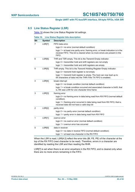
8.5 Line Status Register (LSR)<br />
Table 16 shows the Line Status Register bit settings.<br />
Table 16. Line Status Register bits description<br />
Bit Symbol Description<br />
7 LSR[7] FIFO data error.<br />
logic 0 = no error (normal default condition)<br />
logic 1 = at least one parity error, framing error, or break indication is in the<br />
receiver FIFO. This bit is cleared when no more errors are present in the<br />
FIFO.<br />
6 LSR[6] THR and TSR empty. This bit is the Transmit Empty indicator.<br />
logic 0 = transmitter hold and shift registers are not empty<br />
logic 1 = transmitter hold and shift registers are empty<br />
5 LSR[5] THR empty. This bit is the Transmit Holding Register Empty indicator.<br />
logic 0 = transmit hold register is not empty<br />
logic 1 = transmit hold register is empty. The host can now load up to<br />
<strong>64</strong> characters of data into the THR if the TX FIFO is enabled.<br />
4 LSR[4] break interrupt<br />
logic 0 = no break condition (normal default condition)<br />
logic 1 = a break condition occurred and associated character is 0x00, that<br />
is, RX was LOW for one character time frame<br />
3 LSR[3] framing error<br />
logic 0=noframing error in data being read from RX FIFO (normal default<br />
condition).<br />
logic 1 = framing error occurred in data being read from RX FIFO, that is,<br />
received data did not have a valid stop bit<br />
2 LSR[2] parity error.<br />
logic 0 = no parity error (normal default condition)<br />
logic 1 = parity error in data being read from RX FIFO<br />
1 LSR[1] overrun error<br />
logic 0 = no overrun error (normal default condition)<br />
logic 1 = overrun error has occurred<br />
0 LSR[0] data in receiver<br />
logic 0 = no data in receive FIFO (normal default condition)<br />
logic 1 = at least one character in the RX FIFO<br />
When the LSR is read, LSR[4:2] reflect the error bits (BI, FE, PE) of the character at the<br />
top of the RX FIFO (next character to be read). Therefore, errors in a character are<br />
identified by reading the LSR and then reading the RHR.<br />
LSR[7] is set when there is an error anywhere in the RX FIFO, and is cleared only when<br />
there are no more errors remaining in the FIFO.<br />
<strong>SC16IS740</strong>_<strong>750</strong>_<strong>760</strong>_6<br />
© NXP B.V. 2008. All rights reserved.<br />
Product data sheet Rev. 06 — 13 May 2008 26 of 62