
You also want an ePaper? Increase the reach of your titles
YUMPU automatically turns print PDFs into web optimized ePapers that Google loves.
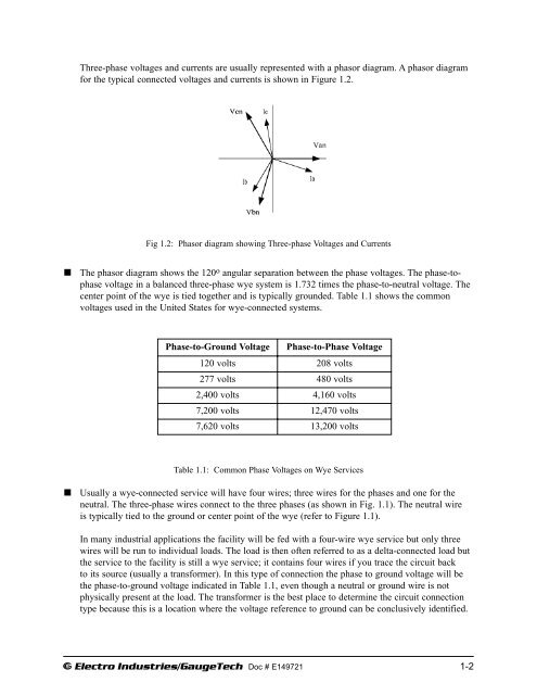
Three-phase voltages and currents are usually represented with a phasor diagram. A phasor diagram<br />
for the typical connected voltages and currents is shown in Figure 1.2.<br />
Fig 1.2: Phasor diagram showing Three-phase Voltages and Currents<br />
<br />
The phasor diagram shows the 120 o angular separation between the phase voltages. The phase-tophase<br />
voltage in a balanced three-phase wye system is 1.732 times the phase-to-neutral voltage. The<br />
center point of the wye is tied together and is typically grounded. Table 1.1 shows the <strong>com</strong>mon<br />
voltages used in the United States for wye-connected systems.<br />
Phase-to-Ground Voltage Phase-to-Phase Voltage<br />
120 volts<br />
208 volts<br />
277 volts<br />
480 volts<br />
2,400 volts<br />
4,160 volts<br />
7,200 volts<br />
12,470 volts<br />
7,620 volts 13,200 volts<br />
Table 1.1: Common Phase Voltages on Wye Services<br />
<br />
Usually a wye-connected service will have four wires; three wires for the phases and one for the<br />
neutral. The three-phase wires connect to the three phases (as shown in Fig. 1.1). The neutral wire<br />
is typically tied to the ground or center point of the wye (refer to Figure 1.1).<br />
In many industrial applications the facility will be fed with a four-wire wye service but only three<br />
wires will be run to individual loads. The load is then often referred to as a delta-connected load but<br />
the service to the facility is still a wye service; it contains four wires if you trace the circuit back<br />
to its source (usually a transformer). In this type of connection the phase to ground voltage will be<br />
the phase-to-ground voltage indicated in Table 1.1, even though a neutral or ground wire is not<br />
physically present at the load. The transformer is the best place to determine the circuit connection<br />
type because this is a location where the voltage reference to ground can be conclusively identified.<br />
e Electro Industries/GaugeTech Doc # E149721 1-2