
You also want an ePaper? Increase the reach of your titles
YUMPU automatically turns print PDFs into web optimized ePapers that Google loves.
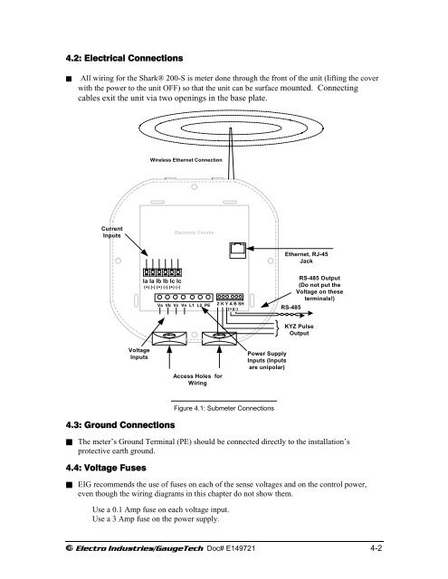
4.2: Electrical Connections<br />
All wiring for the <strong>Shark</strong>® 200-S is meter done through the front of the unit (lifting the cover<br />
with the power to the unit OFF) so that the unit can be surface mounted. Connecting<br />
cables exit the unit via two openings in the base plate.<br />
Wireless Ethernet Connection<br />
Current<br />
Inputs<br />
Electronic Circuits<br />
Ethernet, RJ-45<br />
Jack<br />
Ia Ia Ib Ib Ic Ic<br />
(+) (-) (+) (-) (+) (-)<br />
Va Vb Vc Vn L1 L2 PE<br />
Z K Y A B SH<br />
(+)(-)<br />
RS-485 Output<br />
(Do not put the<br />
Voltage on these<br />
terminals!)<br />
RS-485<br />
KYZ Pulse<br />
Output<br />
Voltage<br />
Inputs<br />
Access Holes for<br />
Wiring<br />
Power Supply<br />
Inputs (Inputs<br />
are unipolar)<br />
4.3: Ground Connections<br />
Figure 4.1: Submeter Connections<br />
The meter’s Ground Terminal (PE) should be connected directly to the installation’s<br />
protective earth ground.<br />
4.4: Voltage Fuses<br />
EIG re<strong>com</strong>mends the use of fuses on each of the sense voltages and on the control power,<br />
even though the wiring diagrams in this chapter do not show them.<br />
Use a 0.1 Amp fuse on each voltage input.<br />
Use a 3 Amp fuse on the power supply.<br />
E Electro Industries/GaugeTech Doc# E149721 4-2