- Page 1 and 2:
User Manual YBA250 Antenna and Tran
- Page 3:
WARRANTY Tektronix warrants that th
- Page 6 and 7:
Table of Contents Reference Measure
- Page 8 and 9:
Table of Contents Appendix D: Upgra
- Page 10 and 11:
Table of Contents Figure 2-11: Read
- Page 12 and 13:
Table of Contents Tables Table i: S
- Page 14 and 15:
Table of Contents x YBA250 Antenna
- Page 16 and 17:
Preface User-defined calibration
- Page 18 and 19:
Preface Additional Information The
- Page 20 and 21:
Preface xvi YBA250 Antenna and Tran
- Page 22 and 23:
General Safety Summary Safety Terms
- Page 25 and 26:
Getting Started This section descri
- Page 27 and 28:
Getting Started 1 2 3 4 5 6 7 Figur
- Page 29 and 30:
Getting Started Attach bus cover Ti
- Page 31 and 32:
Getting Started Batteries Installin
- Page 33 and 34:
Getting Started NOTE. The battery e
- Page 35 and 36:
Getting Started Powering On the Ins
- Page 37 and 38:
Getting Started Shutdown Mode To co
- Page 39 and 40:
Getting Started Use your own good
- Page 41 and 42:
Getting Started To install the tilt
- Page 43:
Operating Basics
- Page 46 and 47:
Operating Basics Icons Double-tap d
- Page 48 and 49:
Operating Basics Getting Help To op
- Page 50 and 51:
Operating Basics Setting the YBA250
- Page 52 and 53:
Operating Basics Command Bar Area T
- Page 54 and 55:
Operating Basics Table 2- 4: Tuning
- Page 56 and 57:
Operating Basics Instrument Area Ic
- Page 58 and 59:
Operating Basics Table 2- 7: The Fi
- Page 60 and 61:
Operating Basics Table 2- 10: The T
- Page 62 and 63:
Operating Basics 2-18 YBA250 Antenn
- Page 64 and 65:
Connecting a Signal The second type
- Page 66 and 67:
Connecting a Signal Figure 2- 6: TE
- Page 68 and 69:
Measurement Overview Two-port inser
- Page 70 and 71:
Calibration and Normalization When
- Page 72 and 73:
Calibration and Normalization What
- Page 74 and 75:
Calibration and Normalization 3. Ca
- Page 76 and 77:
Calibration and Normalization Figur
- Page 78 and 79:
Calibration and Normalization Savin
- Page 80 and 81:
Calibration and Normalization Using
- Page 82 and 83:
Calibration and Normalization Table
- Page 84 and 85:
Calibration and Normalization Norma
- Page 86 and 87:
Calibration and Normalization Table
- Page 88 and 89:
Calibration and Normalization UnNor
- Page 90 and 91:
Calibration and Normalization 7. Ta
- Page 92 and 93:
Calibration and Normalization 3. Ta
- Page 94 and 95:
Calibration and Normalization Norma
- Page 96 and 97:
Calibration and Normalization 2-52
- Page 98 and 99:
Configuring the Instrument 3. To en
- Page 100 and 101:
Configuring the Instrument Setting
- Page 102 and 103:
Configuring the Instrument 3. To di
- Page 104 and 105:
Configuring the Instrument NOTE. Th
- Page 106 and 107:
Configuring the Instrument Connecti
- Page 108 and 109:
Configuring the Instrument 2-64 YBA
- Page 111 and 112:
Setting the Signal Standards and Te
- Page 113 and 114:
Setting the Signal Standards and Te
- Page 115 and 116:
Setting the Signal Standards and Te
- Page 117 and 118:
Measuring Return Loss and VSWR The
- Page 119 and 120:
Measuring Return Loss and VSWR If
- Page 121 and 122:
Measuring Return Loss and VSWR Meas
- Page 123 and 124:
Measuring the Distance to a Fault T
- Page 125 and 126:
Measuring the Distance to a Fault F
- Page 127 and 128:
Measuring the Distance to a Fault T
- Page 129 and 130:
Measuring the Distance to a Fault C
- Page 131 and 132:
Measuring the Distance to a Fault C
- Page 133 and 134:
Measuring the Distance to a Fault R
- Page 135 and 136:
Measuring Insertion Gain and Loss T
- Page 137 and 138:
MeasuringInsertionGainandLoss To me
- Page 139 and 140:
MeasuringInsertionGainandLoss Requi
- Page 141 and 142:
Generating a Continuous Wave (CW) S
- Page 143 and 144:
Working with Traces The YBA250 enab
- Page 145 and 146:
Working with Traces You can also se
- Page 147 and 148:
Working with Traces To save a trace
- Page 149 and 150:
Working with Traces Figure 3- 19: D
- Page 151 and 152:
Working with Traces Figure 3- 21: S
- Page 153 and 154:
Using Markers and Band Edge Cursors
- Page 155 and 156:
Using Markers and Band Edge Cursors
- Page 157 and 158:
Using Markers and Band Edge Cursors
- Page 159 and 160:
Using Markers and Band Edge Cursors
- Page 161 and 162:
Mask Testing Mask testing is used t
- Page 163 and 164:
Mask Testing Table 3- 5: Mask maker
- Page 165 and 166:
Mask Testing Adding a Trace to a Ma
- Page 167 and 168:
Mask Testing If you accidentally d
- Page 169 and 170: Mask Testing The YBA250 calculates
- Page 171 and 172: Saving and Recalling Results, Scree
- Page 173 and 174: Saving and Recalling Results, Scree
- Page 175 and 176: Saving and Recalling Results, Scree
- Page 177 and 178: Saving and Recalling Results, Scree
- Page 179 and 180: Saving and Recalling Results, Scree
- Page 181 and 182: Saving and Recalling Results, Scree
- Page 183: Appendices
- Page 186 and 187: Appendix A: Specifications Table A-
- Page 188 and 189: Appendix A: Specifications Table A-
- Page 190 and 191: Appendix A: Specifications Table A-
- Page 192 and 193: Appendix A: Specifications Table A-
- Page 194 and 195: Appendix A: Specifications Table A-
- Page 196 and 197: Appendix B: Accessories Optional Ac
- Page 198 and 199: Appendix C: Options C-2 YBA250 Ante
- Page 200 and 201: Appendix D: Upgrading/Reinstalling
- Page 202 and 203: Appendix E: Functional Verification
- Page 204 and 205: Appendix E: Functional Verification
- Page 206 and 207: Appendix E: Functional Verification
- Page 208 and 209: Appendix F: Supported Signal Standa
- Page 210 and 211: Appendix F: Supported Signal Standa
- Page 212 and 213: Appendix F: Supported Signal Standa
- Page 214 and 215: Appendix G: Customizing the Channel
- Page 216 and 217: Appendix G: Customizing the Channel
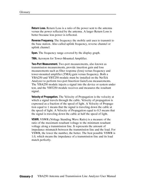
- Page 219: Glossary BMP - Graphics File Format
- Page 224 and 225: Index D DC power adapter, 1-6 Defau
- Page 226 and 227: Index Tools, 2-16 View, 2 -14 Metho
- Page 228: Index T taskbar, desktop, 2-2 Techn


