
Create successful ePaper yourself
Turn your PDF publications into a flip-book with our unique Google optimized e-Paper software.
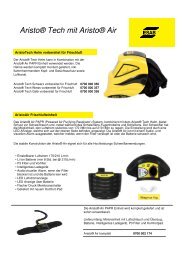
Figure 8. FCAW of a lifting trunnion.<br />
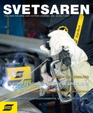
Figure 9. SAW on a lifting trunnion.<br />
Foundation piles<br />
The foundation piles are pre-fabricated by Sif<br />
Group bv, arriving in 83-93 m lengths. To achieve<br />
their final length of 170 –190 m, they need to be<br />
welded together (Figure 10 and 11). This is again<br />
done by FCAW with PZ6138, but here it is<br />
mechanised welding with ESAB Railtrac equipment.<br />
The joint configuration is adapted to this<br />
method -an unsymmetrical X-joint with most of<br />
the weld volume on the outside. The inside part is<br />
welded manually, vertically-up. The root pass is<br />
deposited on ceramic backing. After removal of<br />
the fit-up plates, the majority of the weld volume<br />
is mechanised welded from the outside, verticallyup<br />
from 6 to 12 ‘o clock, mostly with a slight<br />
weaving motion. Welding parameters are adapted<br />
to the several clock positions by the operators.<br />
Dimensional control and weld finish<br />
Normal offshore fabrication, eg, a jacket on top of<br />
which the deck and operational facilities are placed,<br />
is naturally, subject to strict dimensions, but it is<br />
more forgiving than in the case of the Tombua<br />
Landana project. The fact is that three<br />
substructures, fabricated by three different yards,<br />
are stacked on top of each other in almost 400 m<br />
deep waters - and simply have to fit. This places<br />
extremely high demands on the dimensional control<br />
– roughly 3 times as high as normally required.<br />
This is as equally valid for the fabrication of the<br />
TBT’s components – the pile sleeve clusters and<br />
the rows – as it is for the assembly of the super<br />
structure. To exemplify the dimensional control<br />
and its implications for welding, we return to the<br />
fabrication of the pile sleeve clusters, shown in<br />
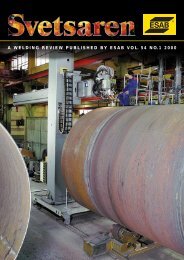
Figure 12.<br />
This image shows the completed pile sleeve cluster<br />
and the nominal distances between the centre<br />
lines of the pile sleeves and the centre line of the<br />
main leg (5172.5 and 5173 mm). The maximum<br />
acceptable tolerance on these distances is 3 mm.<br />
A similar small tolerance is valid on the distances<br />
between the pile sleeves themselves, in the X and<br />
Y directions and on the mutual distances into the<br />
Z direction. This dimensional control is the key<br />
requirement, and everything else is subject to it.<br />
Ideally, the pre-fabricated yoke plates, including<br />
K-bevel, fit exactly, so that there is a constant<br />
root gap between the pile sleeves/main leg and<br />
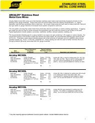
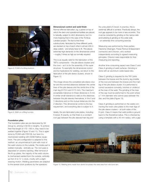
Figure 10. Welding tents made from shrink foil protect the weld area from wind and rain.<br />
the yoke plate’s K-bevel. In practice, this is<br />
extremely difficult to achieve. Practically always, the<br />
root gap appears to be more or less eccentric. This<br />
must be corrected by grinding on the narrow side<br />
and buttering & grinding on the wider side<br />
– an extremely time consuming exercise.<br />
Measuring was performed by three parties;<br />
Heerema Vlissingen, Passe-Partout (independent<br />
contractor) and Chevron, who worked<br />
independently according to agreed measuring<br />
principles. Chevron were responsible for final<br />
measuring and reporting.<br />
Another time-consuming aspect was Class C and<br />
Class A grinding of weld surfaces. Grinding is<br />
done with an aluminium oxide based disc.<br />
Class C grinding is required for the TKY joints<br />
between the braces and the dummy leg (middle<br />
of the row) and between the braces and the main<br />
leg of the pile sleeve cluster. It is performed to<br />
correct excessive convexity, notches or undercut<br />
at the toes of the weld. The grinding of the toes<br />
of the cap must be performed to the point where<br />
a 1 mm diameter wire cannot pass between the<br />
disc and the plate (Figure 13).<br />
Class A grinding is performed on the welds connecting<br />
the lower yoke plates to the main legs of<br />
the pile sleeve clusters – at both sides of the<br />
K-joint. Class A means that weld profile is ground<br />
back to the theoretical radius. This is checked by<br />
using a template with a 45 mm radius, with a gap<br />
12 - <strong>Svetsaren</strong> no. 1 - <strong>2008</strong>