
You also want an ePaper? Increase the reach of your titles
YUMPU automatically turns print PDFs into web optimized ePapers that Google loves.
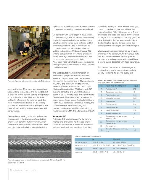
Figure. 2. Welding with one of the automatic TIG stations.<br />
important factors. Most parts are manufactured<br />
using welding technologies and the welded joint<br />
is often the crucial element defining the operational<br />
capability of the part. Also, with the limited<br />
weldability of some of the materials used, the<br />
most important consideration for the welding<br />
specialist is the selection of the appropriate and<br />
most efficient welding process, equipment and<br />
consumables.<br />
Electron-beam welding is the principal welding<br />
process used in the fabrication of gas-turbine<br />
engines. It is performed under vacuum, which<br />
protects the weld pool and facilitates weld metal<br />
strength, deformation being minimal due to the<br />
highly concentrated heat source. However, for many<br />
components, arc welding processes are preferred.<br />
Co-operation with ESAB began in 1995, when<br />
company management set the task of increasing<br />
production output and reducing welding costs.<br />
ESAB specialists carried out a technical audit of<br />
the welding methods used in production. Its<br />
conclusion was that, without up-to-date arc<br />
welding technologies - MMA and manual TIG<br />
welding being the main arc welding processes –<br />
results were high weld metal consumption and<br />
unnecessarily low overall productivity.<br />
Also, repair rates were high because the superior<br />
weld quality standard was hard to meet - even by<br />
qualified welders.<br />
The audit resulted in a recommendation for<br />
investment in programmable automatic TIG<br />
systems, programmable pulse inverter power<br />
sources and the replacement of MMA welding by<br />
MIG/MAG and cored wire welding (FCAW),<br />
wherever possible. In response to this, Zorya-<br />
Mashproekt acquired two ESAB automatic TIG<br />
systems, consisting of a MKR-300 column &<br />
boom, A 25 TIG welding head and A2 Minimaster<br />
GMAW head, PEG1 control unit, AristoMig 500<br />
power source (today named AristoMig 5000i) and<br />
PEMA-1500 positioners. For manual welding, the<br />
company bought various AristoMig 500<br />
multi-process inverters with U8 control unit – one<br />
machine covering MMA, TIG, MIG/MAG and FCAW.<br />
Automatic TIG<br />
Automatic TIG welding is used for the circumferential<br />
and longitudinal welds in gas turbine<br />
bodies in 3-8 mm thick austenitic or martensitic<br />
stainless steel or nickel-base alloys. It involves<br />
pulsed TIG welding of I-joints without a root gap,<br />
onto a copper backing bar, and without filler<br />
material addition. Plate thicknesses up to 3 mm<br />
are welded one-sided and, above 3 mm, two-sided.<br />
Argon is both shielding and backing gas – the<br />
latter flowing into the root area through holes in<br />
the backing bar. Special devices ensure tight<br />
clamping of the weld edges onto the backing bar.<br />
Welding parameters and sequence are pre-programmed<br />
in the control unit, for the various materials<br />
and plate thicknesses. Table 1 gives an<br />
example of actual parameter settings and Figure<br />
3 shows a weld deposited with these parameters.<br />
This method has a number of advantages, in<br />
addition to a dramatic increase in productivity.<br />
By fully controlling the arc, the quality and<br />
Table 1. Parameters for automatic pulse TIG welding of<br />
steel (347) with 3 mm wall thickness.<br />
No Parameters of welding mode Value<br />
1. Pulse current, A 210<br />
2. Background current, A 40<br />
3. Pulse duration, sec. 0.40<br />
4. Inter-pulse time, sec. 0.42<br />
5. Upslope, sec. 0.1<br />
6. Downslope, sec. 0.8<br />
7. Gas pre-flow, sec. 1.0<br />
8. Gas post-flow, sec. 5.0<br />
9. Travel speed, cm/min 18<br />
10.<br />
Consumption of argon for gas<br />
shielding, l/min.<br />
11.<br />
Consumption of argon for gas<br />
backing, l/min.<br />
4<br />
12. Arc length, mm 2<br />
13.<br />
Diameter of tungsten electrode,<br />
mm.<br />
8<br />
4.0<br />
Table 2. Consumables classifications.<br />
EN<br />
SFA/AWS<br />
FILARC PZ6166 12073: T 13 4 M A5.9: EC410NiMo<br />
OK Tubrod 14.31 12073: T 19 12 3 L R M 3 A5.22: E316LT0-1, E316LT0-4<br />
OK 68.25 1600: E 13 4 B 4 2 A5.4: E410NiMo-15<br />
OK 63.30 1600: E 19 12 3 L R 12 A5.4: E316L-17<br />
Figure. 3. Appearance of a weld deposited by automatic TIG welding with the<br />
parameters of Table 1.<br />
24 - <strong>Svetsaren</strong> no. 1 - <strong>2008</strong>