
You also want an ePaper? Increase the reach of your titles
YUMPU automatically turns print PDFs into web optimized ePapers that Google loves.
typically for cryogenic applications down to<br />
-196°C. Here the liquefied natural gas, arriving in<br />
LNG tankers, is stored and held at a temperature<br />
of -163°C at a pressure slightly above atmospheric.<br />
For distribution, the LNG is re-gasified by heat<br />
exchange with sea water, odorised and transported<br />
through the pipeline network at a pressure of<br />
70-100 bar.<br />
The thickness of the tank bottom plates is 6mm,<br />
and the stringer plate 10mm. The metal plates for<br />
the primary tank - in contact with the liquid - vary<br />
in thickness from 16.6mm (at the bottom) to<br />
12mm (at the top), compensating for the<br />
hydrostatic pressure from the stored liquid, which<br />
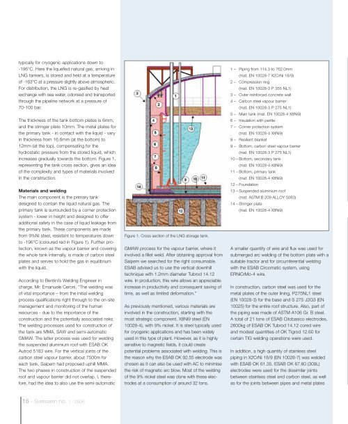
increases gradually towards the bottom. Figure 1,<br />
representing the tank cross section, gives an idea<br />
of the complexity and types of materials involved<br />
in the construction.<br />
Materials and welding<br />
The main component is the primary tank<br />
designed to contain the liquid natural gas. The<br />
primary tank is surrounded by a corner protection<br />
system - lower in height and designed to offer<br />
additional safety in the case of liquid leakage from<br />
the primary tank. These components are made<br />
from 9%Ni steel, resistant to temperatures down<br />
to -196°C (coloured red in Figure 1). Further protection,<br />
known as the vapour barrier and covering<br />
the whole tank internally, is made of carbon steel<br />
plates and serves to hold the gas in equilibrium<br />
with the liquid.<br />
According to Bentini’s Welding Engineer in<br />
charge, Mr. Emanuele Ceroni, “The welding was<br />
of vital importance – from the initial welding<br />
process qualifications right through to the on-site<br />
management and monitoring of the human<br />
resources - due to the importance of the<br />
construction and the potentially associated risks.<br />
The welding processes used for construction of<br />
the tank are MMA, SAW and semi-automatic<br />
GMAW. The latter process was used for welding<br />
the suspended aluminium roof with ESAB OK<br />
Autrod 5183 wire. For the vertical joints of the<br />
carbon steel vapour barrier, about 7500m for<br />
each tank, Saipem had proposed uphill MMA.<br />
The two phases in construction of the suspended<br />
roof and vapour barrier did not overlap. I, therefore,<br />
had the idea to also use the semi-automatic<br />
Figure 1. Cross section of the LNG storage tank.<br />
GMAW process for the vapour barrier, where it<br />
involved a fillet weld. After obtaining approval from<br />
Saipem we searched for the right consumable.<br />
ESAB advised us to use the vertical downhill<br />
technique with 1.2mm diameter Tubrod 14.12<br />
wire. In production, this wire allows an appreciable<br />
increase in productivity and consequent saving of<br />
time, as well as limited deformation.”<br />
As previously mentioned, various materials are<br />
involved in the construction, starting with the<br />
most strategic component, X8Ni9 steel (EN<br />
10028-4), with 9% nickel. It is steel typically used<br />
for cryogenic applications and has been widely<br />
used in this type of plant. However, as it is highly<br />
sensitive to magnetic fields, it could create<br />
potential problems associated with welding. This is<br />
the reason why the ESAB OK 92.55 electrode was<br />
chosen as it can also be used with AC to minimise<br />
the risk of magnetic arc blow. Most of the welding<br />
of the 9% nickel steel was done with these electrodes<br />
at a consumption of around 32 tons.<br />
1 – Piping from 114.3 to 762.0mm<br />
(mat. EN 10028-7 X2CrNi 18/9)<br />
2 – Compression ring<br />
(mat. EN 10028-3 P 355 NL1)<br />
3 – Outer reinforced concrete wall<br />
4 – Carbon steel vapour barrier<br />
(mat. EN 10028-3 P 275 NL1)<br />
5 – Main tank (mat. EN 10028-4 X8Ni9)<br />
6 – Insulation with perlite<br />
7 – Corner protection system<br />
(mat. EN 10028-4 X8Ni9)<br />
8 – Resilient blanket<br />
9 – Bottom, carbon steel vapour barrier<br />
(mat. EN 10028-3 P 275 NL1)<br />
10 – Bottom, secondary tank<br />
(mat. EN 10028-4 X8Ni9)<br />
11 – Bottom, primary tank<br />
(mat. EN 10028-4 X8Ni9)<br />
12 – Foundation<br />
13 – Suspended aluminium roof<br />
(mat. ASTM B 209 ALLOY 5083)<br />
14 – Stringer plate<br />
(mat. EN 10028-4 X8Ni9)<br />
A smaller quantity of wire and flux was used for<br />
submerged arc welding of the bottom plate with a<br />
suitable tractor and for circumferential welding<br />
with the ESAB Circomatic system, using<br />
ERNiCrMo-4 wire.<br />
In construction, carbon steel was used for the<br />
metal plates of the outer lining, P275NL1 steel<br />
(EN 10028-3) for the base and S 275 J2G3 (EN<br />
10025) for the entire roof structure. Also, part of<br />
the piping was made of ASTM A106 Gr. B steel.<br />
A total of 21 tons of ESAB Citobasico electrodes,<br />
2600kg of ESAB OK Tubrod 14.12 cored wire<br />
and modest quantities of OK Tigrod 12.60 for<br />
certain TIG welding operations were used.<br />
In addition, a high quantity of stainless steel<br />
piping in X2CrNi 18/9 (EN 10028-7) was welded<br />
with ESAB OK 61.35. ESAB OK 67.60 (309L)<br />
electrodes were used for the dissimilar joints<br />
between stainless steel and carbon steel, as well<br />
as for the joints between pipes and metal plates<br />
16 - <strong>Svetsaren</strong> no. 1 - <strong>2008</strong>