HERZ laying system
HERZ laying system
HERZ laying system
You also want an ePaper? Increase the reach of your titles
YUMPU automatically turns print PDFs into web optimized ePapers that Google loves.
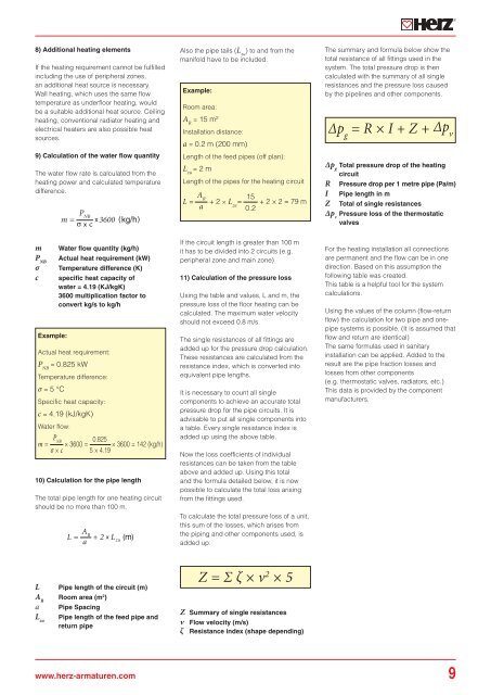
8) Additional heating elements<br />
If the heating requirement cannot be fulfilled<br />
including the use of peripheral zones,<br />
an additional heat source is necessary.<br />
Wall heating, which uses the same flow<br />
temperature as underfloor heating, would<br />
be a suitable additional heat source. Ceiling<br />
heating, conventional radiator heating and<br />
electrical heaters are also possible heat<br />
sources.<br />
9) Calculation of the water flow quantity<br />
The water flow rate is calculated from the<br />
heating power and calculated temperature<br />
difference.<br />
Also the pipe tails (L zu<br />
) to and from the<br />
manifold have to be included.<br />
Example:<br />
Room area:<br />
A R<br />
= 15 m²<br />
Installation distance:<br />
a = 0.2 m (200 mm)<br />
Length of the feed pipes (off plan):<br />
L zu<br />
= 2 m<br />
Length of the pipes for the heating circuit<br />
A<br />
L<br />
R<br />
= + 2 × L<br />
a<br />
= 15<br />
zu<br />
0.2 + 2 × 2 = 79 m<br />
The summary and formula below show the<br />
total resistance of all fittings used in the<br />
<strong>system</strong>. The total pressure drop is then<br />
calculated with the summary of all single<br />
resistances and the pressure loss caused<br />
by the pipelines and other components.<br />
∆p g<br />
= R × I + Z + ∆p v<br />
Δp g<br />
Total pressure drop of the heating<br />
circuit<br />
R Pressure drop per 1 metre pipe (Pa/m)<br />
I Pipe length in m<br />
Z Total of single resistances<br />
Δp v<br />
Pressure loss of the thermostatic<br />
valves<br />
m<br />
P NB<br />
σ<br />
c<br />
Example:<br />
Water flow quantity (kg/h)<br />
Actual heat requirement (kW)<br />
Temperature difference (K)<br />
specific heat capacity of<br />
water = 4.19 (KJ/kgK)<br />
3600 multiplication factor to<br />
convert kg/s to kg/h<br />
Actual heat requirement:<br />
P NB<br />
= 0.825 kW<br />
Temperature difference:<br />
σ = 5 °C<br />
Specific heat capacity:<br />
c = 4.19 (kJ/kgK)<br />
Water flow:<br />
P<br />
m =<br />
NB 0.825<br />
× 3600 = × 3600 = 142 (kg/h)<br />
σ × c 5 × 4.19<br />
10) Calculation for the pipe length<br />
The total pipe length for one heating circuit<br />
should be no more than 100 m.<br />
If the circuit length is greater than 100 m<br />
it has to be divided into 2 circuits (e.g.<br />
peripheral zone and main zone)<br />
11) Calculation of the pressure loss<br />
Using the table and values, L and m, the<br />
pressure loss of the floor heating can be<br />
calculated. The maximum water velocity<br />
should not exceed 0.8 m/s.<br />
The single resistances of all fittings are<br />
added up for the pressure drop calculation.<br />
These resistances are calculated from the<br />
resistance index, which is converted into<br />
equivalent pipe lengths.<br />
It is necessary to count all single<br />
components to achieve an accurate total<br />
pressure drop for the pipe circuits. It is<br />
advisable to put all single components into<br />
a table. Every single resistance index is<br />
added up using the above table.<br />
Now the loss coefficients of individual<br />
resistances can be taken from the table<br />
above and added up. Using this total<br />
and the formula detailed below, it is now<br />
possible to calculate the total loss arising<br />
from the fittings used.<br />
To calculate the total pressure loss of a unit,<br />
this sum of the losses, which arises from<br />
the piping and other components used, is<br />
added up.<br />
For the heating installation all connections<br />
are permanent and the flow can be in one<br />
direction. Based on this assumption the<br />
following table was created.<br />
This table is a helpful tool for the <strong>system</strong><br />
calculations.<br />
Using the values of the column (flow-return<br />
flow) the calculation for two pipe and onepipe<br />
<strong>system</strong>s is possible. (It is assumed that<br />
flow and return are identical)<br />
The same formulas used in sanitary<br />
installation can be applied. Added to the<br />
result are the pipe fraction losses and<br />
losses from other components<br />
(e.g. thermostatic valves, radiators, etc.)<br />
This data is provided by the component<br />
manufacturers.<br />
L Pipe length of the circuit (m)<br />
A R<br />
Room area (m 2 )<br />
a Pipe Spacing<br />
L zu<br />
Pipe length of the feed pipe and<br />
return pipe<br />
Z = Σ ζ × v 2 × 5<br />
Z Summary of single resistances<br />
v Flow velocity (m/s)<br />
ζ Resistance index (shape depending)<br />
www.herz-armaturen.com 9


