Basic Information Selection Guide M451-110, August 2002 - Rexnord
Basic Information Selection Guide M451-110, August 2002 - Rexnord
Basic Information Selection Guide M451-110, August 2002 - Rexnord

You also want an ePaper? Increase the reach of your titles
YUMPU automatically turns print PDFs into web optimized ePapers that Google loves.
F A L K<br />
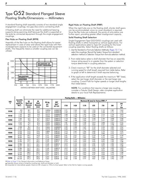
Type G52 Standard Flanged Sleeve<br />
Floating Shafts/Dimensions — Millimeters<br />
A standard floating shaft assembly consists of two standard single<br />
engagement couplings, two gap discs and a connecting shaft.<br />
A floating shaft can eliminate the need for additional bearing<br />
supports along spanning shaft because the shaft is supported at<br />
the ends by connected equipment through the single engagement<br />
couplings.<br />
Flex Hubs on Floating Shaft (RFFR)<br />
Assembly of the flex hubs on the floating shaft allows for easier<br />
replacement in case of wear and allows the rigid hubs with their<br />
increased bore capacity to be used on the connected equipment<br />
shafts. This frequently means a smaller coupling size can be<br />
utilized.<br />
Rigid Hubs on Floating Shaft (FRRF)<br />
When the rigid hubs are on the floating shaft, shorter shaft spans<br />
can be accommodated, since no cover drawback is required.<br />
Since the flex hubs are outboard, the points of articulation are<br />
further apart, providing greater offset misalignment capacity.<br />
Solid Floating Shaft <strong>Selection</strong><br />
Single Engagement Type G52/GV52 couplings are used with<br />
floating shafts in either horizontal or vertical applications. For<br />
vertical applications select a Type GV coupling for the lower<br />
coupling assembly. Select floating shafts as follows:<br />
1. Use the Standard or Formula <strong>Selection</strong> Methods, Pages 10-11 to<br />
select the couplings. Record the System Torque from standard<br />
selection method or <strong>Selection</strong> Torque from formula selection method.<br />
OPERATING SPEED – RPM<br />
2000<br />
1500<br />
1000<br />
500<br />
BALANCING<br />
NORMALLY NOT<br />
REQUIRED<br />
BALANCING OF<br />
SHAFT REQUIRED<br />
254 508 762 1016 1270 1524 1778 2032<br />
DISTANCE BETWEEN SHAFT ENDS – MILLIMETERS<br />
2. From table below select a shaft diameter that has an assembly<br />
torque rating equal to or greater than the system or selection<br />
torque determined in coupling selection.<br />
3. Check maximum “BE” for the shaft diameter selected and<br />
running speed for shaft length required from table below. Refer<br />
to graph at left to determine if shaft requires balancing.<br />
4. If the application shaft length exceeds the maximum “BE” listed,<br />
select the next larger shaft diameter or the next larger size<br />
coupling. Consult Falk for higher speeds or longer shaft lengths<br />
than listed below.<br />
NOTE: For conditions that require a larger size coupling,<br />
consider a Tubular Shaft Design, refer complete application<br />
details to your local Falk Representative.<br />
SIZE<br />
<br />
1010G<br />
1015G<br />
1020G<br />
1025G<br />
1030G<br />
1035G<br />
1040G<br />
1045G<br />
1050G<br />
1055G<br />
1060G<br />
1070G<br />
Assembly<br />
Torque<br />
Rating <br />
Nm †<br />
SB<br />
Shaft End<br />
Diameter<br />
(mm)<br />
SD<br />
Shaft<br />
Diameter<br />
(mm)<br />
Wt-kg<br />
per<br />
mm<br />
WR 2<br />
kgm 2<br />
per mm<br />
Floating Shafts — Millimeters<br />
Maximum BE (mm) for Various RPM’s <br />
1750 1430 1170 870 720 580<br />
493 38,1 39,7 0,00964 0,00000196 1 371 1 524 1 676 1 955 2 159 2 387 2 463<br />
1 139 47,6 50,8 0,0159 0,00000518 1 549 1 727 1 905 2 209 2 438 2 717 2 794<br />
1 169 50,8 54,0 0,0179 0,00000657 1 600 1 778 1 955 2 286 2 514 2 794 2 870<br />
2 349 60,3 76,2 0,0248 0,0000126 1 752 1 930 2 133 2 463 2 717 3 022 3 124<br />
2 282 63,5 66,7 0,0273 0,0000152 1 778 1 981 2 184 2 540 2 794 3 098 3 200<br />
4 271 73,0 95,2 0,0557 0,0000259 1 905 2 108 2 336 2 717 2 971 3 327 3 429<br />
4 463 79,4 82,6 0,0420 0,0000357 1 981 2 209 2 438 2 819 3 098 3 454 3 556<br />
7 474 92,1 95,2 0,0559 0,0000634 2 133 2 362 2 616 3 022 3 237 3 708 3 835<br />
8 508 98,4 101,6 0,0636 0,0000820 2 209 2 438 2 692 3 124 3 454 3 835 3 962<br />
12 101 104,8 127,0 0,0718 0,000104 2 260 2 514 2 794 3 225 3 556 3 962 4 064<br />
13 333 114,3 120,6 0,0896 0,000163 2 413 2 667 2 946 3 403 3 759 4 191 4 292<br />
18 508 123,8 146,0 0,993 0,000200 2 463 2 717 3 022 3 505 3 860 4 292 4 419<br />
24 327 139,7 146,0 0,131 0,000350 2 641 2 921 3 251 3 759 4 140 4 597 4 749<br />
30 609 146,0 165,1 0,143 0,000415 2 692 2 997 3 302 3 835 4 216 4 699 4 851<br />
31 581 152,4 165,1 0,168 0,000572 2 819 3 124 3 454 3 987 4 394 4 902 5 029<br />
41 999 171,5 203,2 0,254 0,00131 3 124 3 454 3 810 4 445 4 876 5 435 5 588<br />
37 886 161,9 165,1 0,168 0,000572 2 819 3 124 3 454 3 987 4 394 4 902 5 029<br />
56 597 187,3 203,2 0,254 0,00131 3 124 3 454 3 810 4 445 4 876 5 435 5 588<br />
37 886 161,9 165,1 0,168 0,000572 2 819 3 124 3 454 3 987 4 394 4 902 5 029<br />
74 031 200,0 203,2 0,254 0,00131 3 124 3 454 3 810 4 445 4 876 5 435 5 588<br />
71 410 200,0 203,2 0,254 0,00131 3 124 3 454 3 810 4 445 4 876 5 435 5 588<br />
90 404 215,9 217,4 0,291 0,00172 3 225 3 581 3 962 4 597 5 054 5 613 5 791<br />
71 410 200,0 203,2 0,254 0,00131 3 124 3 454 3 810 4 445 4 876 5 435 5 588<br />
135 250 241,3 242,8 0,363 0,00268 3 403 3 784 4 191 4 851 5 334 5 943 6 121<br />
Refer to Page 13 for General <strong>Information</strong> and Reference Notes.<br />
Assembly torque rating is limited by coupling size, shaft end diameter or both.<br />
Interpolate for intermediate speeds. Maximum BE is based on 70% of critical speed. Refer to the Falk for higher running speeds.<br />
540<br />
or<br />
less<br />
20 (<strong>M451</strong>-<strong>110</strong>) The Falk Corporation, 1998, <strong>2002</strong>.