Basic Information Selection Guide M451-110, August 2002 - Rexnord
Basic Information Selection Guide M451-110, August 2002 - Rexnord
Basic Information Selection Guide M451-110, August 2002 - Rexnord

Create successful ePaper yourself
Turn your PDF publications into a flip-book with our unique Google optimized e-Paper software.
Engineering Data — Standard Flanged Sleeve & Continuous Sleeve<br />
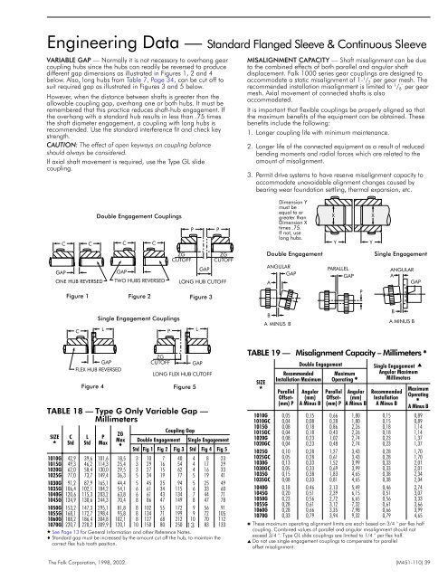
VARIABLE GAP — Normally it is not necessary to overhang gear<br />
coupling hubs since the hubs can readily be reversed to produce<br />
different gap dimensions as illustrated in Figures 1, 2 and 4<br />
below. Also, long hubs from Table 7, Page 34, can be cut off to<br />
suit required gap as illustrated in Figures 3 and 5 below.<br />
However, when the distance between shafts is greater than the<br />
allowable coupling gap, overhang one or both hubs. It must be<br />
remembered that this practice reduces shaft-hub engagement. If<br />
the overhang with a standard hub results in less than .75 times<br />
the shaft diameter engagement, a coupling with long hubs is<br />
recommended. Use the standard interference fit and check key<br />
strength.<br />
CAUTION: The effect of open keyways on coupling balance<br />
should always be considered.<br />
If axial shaft movement is required, use the Type GL slide<br />
coupling.<br />
MISALIGNMENT CAPACITY — Shaft misalignment can be due<br />
to the combined effects of both parallel and angular shaft<br />
displacement. Falk 1000 series gear couplings are designed to<br />
accommodate a static misalignment of 1- 1 / 2° per gear mesh. The<br />
recommended installation misalignment is limited to 1 / 8° per gear<br />
mesh. Axial movement of connected shafts is also<br />
accommodated.<br />
It is important that flexible couplings be properly aligned so that<br />
the maximum benefits of the equipment can be obtained. These<br />
benefits include the following:<br />
1. Longer coupling life with minimum maintenance.<br />
2. Longer life of the connected equipment as a result of reduced<br />
bending moments and radial forces which are related to the<br />
amount of misalignment.<br />
3. Permit drive systems to have reserve misalignment capacity to<br />
accommodate unavoidable alignment changes caused by<br />
bearing wear foundation settling, thermal expansion, etc.<br />
C<br />
C<br />
Double Engagement Couplings<br />
C<br />
C<br />
P<br />
P<br />
Dimension Y<br />
must be<br />
equal to or<br />
greater than<br />
Dimension X<br />
times .75.<br />
If not, use<br />
long hubs.<br />
X<br />
Y<br />
X<br />
Y<br />
GAP<br />
ONE HUB REVERSED<br />
GAP<br />
TWO HUBS REVERSED<br />
ZG<br />
CUTOFF<br />
GAP<br />
ZG<br />
CUTOFF<br />
LONG HUB CUTOFF<br />
Double Engagement<br />
ANGULAR<br />
GAP<br />
A<br />
PARALLEL<br />
GAP<br />
Single Engagement<br />
ANGULAR<br />
A<br />
GAP<br />
Figure 1 Figure 2 Figure 3<br />
P<br />
C<br />
Single Engagement Couplings<br />
L<br />
P<br />
L<br />
B<br />
A MINUS B<br />
B<br />
A MINUS B<br />
TABLE 18 — Type G Only Variable Gap —<br />
Millimeters<br />
SIZE<br />
<br />
C<br />
Std<br />
GAP<br />
FLEX HUB REVERSED<br />
L<br />
Std<br />
P<br />
Max<br />
ZG<br />
Max<br />
<br />
ZG<br />
CUTOFF<br />
Coupling Gap<br />
Double Engagement<br />
GAP<br />
LONG FLEX HUB CUTOFF<br />
Figure 4 Figure 5<br />
Single Engagement<br />
Std Fig 1 Fig 2 Fig 3 Std Fig 4 Fig 5<br />
1010G 42,9 39,6 101,6 18,5 3 10 7 40 4 8 23<br />
1015G 49,3 46,2 114,3 25,4 3 29 16 54 4 17 29<br />
1020G 62,0 58,4 130,0 29,5 3 27 15 62 4 16 33<br />
1025G 77,0 73,7 149,4 36,3 5 34 19 77 5 19 41<br />
1030G 91,2 87,9 165,1 44,4 5 45 25 94 5 25 49<br />
1035G 106,4 102,1 184,2 54,1 6 61 34 115 6 33 60<br />
1040G 120,6 115,3 203,2 63,8 6 61 43 134 7 44 71<br />
1045G 134,9 130,6 244,3 70,4 8 86 47 149 8 47 78<br />
1050G 153,2 147,3 295,1 81,8 8 102 55 172 9 56 91<br />
1055G 168,1 172,7 298,4 95,8 8 134 71 199 9 72 105<br />
1060G 188,2 186,4 304,8 102,1 8 127 68 212 10 70 112<br />
1070G 220,7 220,2 309,9 120,1 10 150 80 250 13 83 133<br />
See Page 13 for General <strong>Information</strong> and other Reference Notes.<br />
Standard gap must be increased by the amount cut off the hub, to maintain the<br />
correct flex hub tooth position.<br />
TABLE 19 — Misalignment Capacity – Millimeters <br />
SIZE<br />
<br />
Double Engagement<br />
Recommended<br />
Installation Maximum<br />
Parallel<br />
Offset-<br />
(mm) P<br />
Angular<br />
(mm)<br />
A Minus B<br />
Maximum<br />
Operating <br />
Parallel<br />
Offset-<br />
(mm) P<br />
Angular<br />
(mm)<br />
A Minus B<br />
Single Engagement <br />
Angular Maximum<br />
Millimeters<br />
Recommended<br />
Installation<br />
A Minus B<br />
Maximum<br />
Operating<br />
<br />
A Minus B<br />
1010G 0,05 0,15 0,66 1,80 0,15 0,89<br />
1010GC 0,04 0,08 0,28 1,80 0,15 0,89<br />
1015G 0,08 0,18 0,86 2,26 0,18 1,14<br />
1015GC 0,04 0,18 0,43 2,26 0,18 1,14<br />
1020G 0,08 0,23 1,02 2,74 0,23 1,37<br />
1020GC 0,04 0,23 0,48 2,74 0,23 1,37<br />
1025G 0,10 0,28 1,27 3,43 0,28 1,70<br />
1025GC 0,05 0,28 0,61 3,43 0,28 1,70<br />
1030G 0,13 0,33 1,52 3,99 0,33 2,01<br />
1030GC 0,05 0,33 0,69 3,99 0,33 2,01<br />
1035G 0,15 0,38 1,83 4,65 0,38 2,34<br />
1035GC 0,08 0,33 0,81 4,65 0,38 2,34<br />
1040G 0,18 0,46 2,13 5,49 0,46 2,74<br />
1045G 0,20 0,51 2,39 6,15 0,51 3,07<br />
1050G 0,23 0,56 2,72 6,65 0,56 3,33<br />
1055G 0,28 0,61 3,12 7,32 0,61 3,66<br />
1060G 0,28 0,66 3,35 7,98 0,66 3,99<br />
1070G 0,33 0,79 3,94 9,32 0,79 4,65<br />
These maximum operating alignment limits are each based on 3/4 ° per flex half<br />
coupling. Combined values of parallel and angular misalignment should not<br />
exceed 3/4 °. Type GL slide couplings are limited to 1/4 ° per flex half.<br />
Do not use single engagement couplings to compensate for parallel<br />
offset misalignment.<br />
The Falk Corporation, 1998, <strong>2002</strong>. (<strong>M451</strong>-<strong>110</strong>) 39