F A L K Type GV52 Large Flanged Sleeve Vertical Single Engagement/Dimensions — Millimeters IMPORTANT — When couplings are mounted on a floating shaft, do not exceed allowable shaft speed for the assembly, A D F FLEX HUB (TOP POSITION ONLY) MINIMUM CLEARANCE REQUIRED FOR ALIGNING C M B J N CS GAP GASKET LUBRICATE THRU SLEEVE BE L E RIGID HUB K SHAFT CENTERING COMPONENTS SIZE Torque Rating (Nm) † (millions) 1000 2000 Series Series Allow Speed rpm Max Bore One Rect Key (mm) Flex Hub Rigid Hub Min Bore Both Hubs (mm) Cplg Wt. With No Bore (kg) Lube Wt (kg) DIMENSIONS — Millimeters A B C D E F J K L M N BE CS Gap 1080/2080G 0,170 0,234 1750 266 340 101,60 699 4,99 590,6 511,6 236,7 355,6 7,9 571,5 242,8 450,8 248,9 287,3 368,3 38,6 224,0 26 1090/2090G 0,226 0,315 1550 290 380 114,30 984 6,35 660,4 567,2 261,9 393,7 7,9 641,4 265,2 508,0 275,8 314,5 419,1 42,2 249,2 29 <strong>110</strong>0/2100G 0,310 0,443 1450 320 400 127,00 1252 7,71 711,2 625,3 288,8 444,5 9,7 698,5 293,6 530,4 304,8 339,9 469,9 48,3 273,1 33 1<strong>110</strong>/2<strong>110</strong>G 0,413 0,609 1330 373 440 139,70 1637 9,07 774,7 682,8 317,2 495,3 9,7 749,3 322,3 584,2 333,2 368,3 520,7 48,3 301,5 33 1120/2120G 0,555 0,777 1200 400 483 152,40 2077 10,9 838,2 721,4 336,6 546,1 9,7 825,5 341,4 647,7 352,3 387,4 571,5 48,3 320,8 33 1130/2130G 0,719 0,925 1075 440 500 165,10 2572 16,8 911,4 762,0 352,0 584,2 9,7 886,0 362,0 708,2 371,3 419,1 609,6 54,9 336,3 39 1140/2140G 0,911 1,140 920 460 535 177,80 3062 17,2 965,2 806,4 373,9 635,0 9,7 939,8 378,0 749,3 393,7 441,5 660,4 54,9 358,1 39 1150/2150G 1,100 1,350 770 490 580 190,50 3751 20,9 1 028,7 857,2 399,8 685,8 9,7 1 003,3 407,9 812,8 419,1 466,9 711,2 54,9 384,0 39 1160/2160G 1,310 1,640 650 525 630 254,00 4631 21,8 1 111,2 908,0 416,1 736,6 12,7 1 085,8 419,1 886,0 441,5 482,6 762,0 70,4 397,0 51 1180/2180G 1,660 2,140 480 600 710 285,75 6069 25,4 1 219,2 939,8 431,8 838,2 12,7 1 193,8 434,8 993,6 457,2 501,6 863,6 70,4 412,8 51 1200/2200G 2,140 2,850 370 660 780 317,50 8482 34,5 1 358,9 1 098,6 511,0 927,1 12,7 1 308,1 514,4 1 095,2 536,4 616,0 965,2 70,4 492,3 51 1220/2220G 2,720 3,560 290 725 890 349,25 11 680 54,4 1 511,3 1 196,8 555,8 1 016,0 15,7 1 473,2 565,2 1 244,6 584,2 660,4 1 066,8 83,3 530,4 58 1240/2240G 3,470 4,480 270 810 940 381,00 14 388 56,7 1 632,0 1 285,7 599,9 1 130,3 15,7 1 581,2 606,6 1 314,7 628,6 698,5 1 168,4 83,3 574,5 58 1260/2260G 4,490 5,480 250 880 1 015 412,75 17 722 61,2 1 746,2 1 374,6 644,7 1 231,9 15,7 1 695,4 647,7 1 422,4 673,1 749,3 1 270,0 83,1 619,3 58 1280/2280G 5,840 6,760 230 950 1 090 444,50 21 <strong>110</strong> 70,3 1 866,9 1 412,7 663,4 1 333,5 15,7 1 803,4 666,8 1 530,6 691,9 768,4 1 371,6 83,1 638,0 58 1300/2300G 6,760 8,190 220 1 025 1 170 476,25 24 712 77,1 1 974,8 1 450,8 682,8 1 435,1 15,7 1 911,4 685,8 1 638,3 711,2 774,7 1 473,2 83,1 657,4 58 See Page 13 for General <strong>Information</strong> and other Reference Notes. Downward thrust capacity for Sizes 1010 thru 1030GV52 is 4 536 kilograms; Sizes 1035 thru 1070GV52 is 13 608 kilograms and Size 1080GV52 and larger is 39 463 kilograms. Reduced shank diameter hubs are available where required bore permits. See Table 28, Page 51 for selections. Dimension K maybe an “as cast” surface depending upon coupling size and bore. Note: There is no standardization of metric keys and keyways for bores greater than 500 mm. Maximum bores for flex hubs 1150G and larger and rigid hubs 1130G and larger are based on a hub diameter to bore ratio of 1.4. See also 457-130. Sizes thru 1140G flex hubs and 1120G rigid hubs are in agreement with that engineering sheet. 44 (<strong>M451</strong>-<strong>110</strong>) The Falk Corporation, 1998, <strong>2002</strong>.
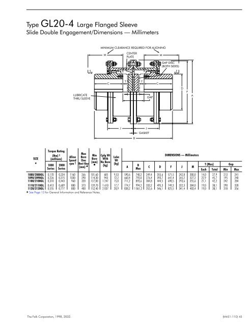
Type GL20-4 Large Flanged Sleeve Slide Double Engagement/Dimensions — Millimeters MINIMUM CLEARANCE REQUIRED FOR ALIGNING M CENTER PLATE M GAP DISC (BOTH SIDES) LUBRICATE THRU SLEEVE C T T GAP C D F A J B J GASKET SIZE Torque Rating (Nm) † (millions) 1000 Series 2000 Series Allow Speed rpm † Max Bore One Rect Key (mm) Min Bore (mm) Cplg Wt With No Bore (kg) Lube Wt (kg) A B Max DIMENSIONS — Millimeters C D F J M T (Max) Gap Each Total Min Max 1080/2080GL 0,170 0,234 1160 266 101,60 685 9,53 590,6 740,2 249,4 355,6 571,5 242,8 300,0 14,0 27,9 213 241 1090/2090GL 0,226 0,315 1030 290 114,30 943 12,2 660,4 793,0 276,4 393,7 641,4 265,2 327,2 22,9 45,7 195 240 <strong>110</strong>0/2100GL 0,310 0,443 960 320 127,00 1 247 15,0 711,2 893,6 304,8 444,5 698,5 293,6 355,6 21,1 42,2 242 284 1<strong>110</strong>/2<strong>110</strong>GL 0,413 0,609 880 373 139,70 1 610 17,7 774,7 994,2 333,2 495,3 749,3 322,3 384,0 19,0 38,1 290 328 1120/2120GL 0,555 0,777 800 400 152,40 2 037 20,9 838,2 1 061,2 352,6 546,1 825,5 341,4 403,4 19,0 38,1 318 356 See Page 13 for General <strong>Information</strong> and Reference Notes. The Falk Corporation, 1998, <strong>2002</strong>. (<strong>M451</strong>-<strong>110</strong>) 45