Basic Information Selection Guide M451-110, August 2002 - Rexnord
Basic Information Selection Guide M451-110, August 2002 - Rexnord
Basic Information Selection Guide M451-110, August 2002 - Rexnord

Create successful ePaper yourself
Turn your PDF publications into a flip-book with our unique Google optimized e-Paper software.
F A L K<br />
How to Select<br />
Standard <strong>Selection</strong> Method<br />
The standard selection method can be used for most motor,<br />
turbine, or engine driven applications. The following information<br />
is required to select a gear coupling.<br />
Kilowatt (kW) or torque (Nm)<br />
Running rpm.<br />
Application or type of equipment to be connected (motor to<br />
pump, drive to conveyor, etc.).<br />
Shaft diameters.<br />
Shaft gaps.<br />
Physical space limitations<br />
Special bore or finish information and type of fit<br />
Exceptions are High Peak Loads, Brake Applications or high<br />
frequency axial sliding (greater than 5 per hour). For these<br />
conditions, use the Formula <strong>Selection</strong> Method on the next<br />
page. Applications that require rapid changes in direction<br />
or torque reversals should be referred to Falk.<br />
1. RATING: Determine system torque. If torque is not given,<br />
calculate as shown below.<br />
System Torque (Nm) =<br />
kW x 9549<br />
rpm<br />
Where: kW (Kilowatt) is the actual or transmitted power<br />
required by the application (if unknown, use the motor or<br />
turbine nameplate rating) and rpm is the actual speed the<br />
coupling is rotating.<br />
2. SERVICE FACTOR: Determine the appropriate service factor<br />
from Tables 2 and 3, Page 12 or Table 4, Page 13.<br />
3. REQUIRED MINIMUM COUPLING RATING: Determine the<br />
required minimum coupling rating as shown below<br />
Minimum Coupling Rating = S.F. (Service Factor) x Torque<br />
(Nm)<br />
4. TYPE: Refer to Pages 7-9 and select the appropriate coupling type.<br />
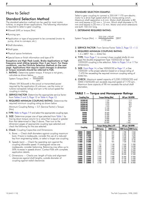
5. SIZE: Determine proper size of type selected from Table 1 by<br />
tracing down torque column to a value that is equal or greater<br />
than that determined in Step 3 above. Then turn to the<br />
dimension pages of appropriate coupling type selected and<br />
check the following for the size selected.<br />
6. Check: Coupling Capacities and Dimensions<br />
A. Bores — Check shaft diameters against coupling maximum<br />
bore. If bore is inadequate, consider the use of a reduced<br />
key from engineering tables, or select a larger size coupling.<br />
B. Speeds (rpm) — Check the operating rpm against the<br />
coupling allowable speed. If catalogued values are<br />
inadequate, consider balancing. Balancing may allow up to<br />
50% increase in speeds shown. Contact Falk with complete<br />
application details.<br />
C. Dimensions — Checks are: length of hubs and alignment<br />
clearances against shaft lengths, outside diameter of<br />
coupling against radial clearances<br />
STANDARD SELECTION EXAMPLE:<br />
Select a gear coupling to connect a 355 kW 1170 rpm electric<br />
motor to a drive high speed shaft of a maneuvering winch.<br />
Maximum shaft separation is 6 mm. Motor shaft diameter is 80<br />
mm and keyway is 22 mm x 14 mm. Winch shaft diameter is 75<br />
mm and keyway is 20 mm x 12 mm. Motor and winch extensions<br />
are both 150 mm long.<br />
1. DETERMINE REQUIRED RATING:<br />
System Torque (Nm) =<br />
355 kW x 9549<br />
1170 rpm<br />
2897<br />
2. SERVICE FACTOR: From Service Factor Table 2, Page 12 =1.5<br />
3. REQUIRED MINIMUM COUPLING RATING:<br />
1.5 x 2897 Nm = 4346 Nm<br />
4. TYPE: From Page 7, to connect close coupled shafts (6 mm<br />
gap) the double engagement Type 1025GC02 or Type<br />
1025G20 coupling is the selection. Refer to Pages 14 or 17 for<br />
dimensions.<br />
5. SIZE: From Page 14, a Size 1025GC02 or Page 17, a Size<br />
1025G20 is the proper selection based on a torque rating of<br />
7 470 Nm exceeding the required minimum coupling rating of<br />
4346 Nm.<br />
6. CHECK: Maximum speed capacity of 3,330 (1025GC02) and<br />
5000 (1025G20) rpm exceeds required speed of 1170 rpm.<br />
Maximum bore capacity of 98 mm exceeds the actual shaft<br />
diameters.<br />
TABLE 1 — Torque and Horsepower Ratings<br />
Coupling Size Torque Rating (Nm) kW per 100 RPM<br />
1010G/GC 1 139 11,9<br />
1015G/GC 2 350 24,6<br />
1020G/GC 4 270 44,9<br />
1025G/GC 7 470 78,3<br />
1030G/GC 12 100 127<br />
1035G/GC 18 500 194<br />
1040G 30 600 321<br />
1045G 42 000 440<br />
1050G 56 600 593<br />
1055G 74 000 776<br />
1060G 90 400 947<br />
1070G 135 000 1 420<br />
Coupling<br />
Torque Rating (Nm) x10 3 kW per 100 RPM<br />
1000 Series 2000 Series 1000 Series 2000 Series<br />
1080G 2080G 170 234 1 780 2 450<br />
1090G 2090G 226 315 2 360 3 300<br />
<strong>110</strong>0G 2100G 310 443 3 250 4 640<br />
1<strong>110</strong>G 2<strong>110</strong>G 413 609 4 330 6 380<br />
1120G 2120G 555 777 5 820 8 140<br />
1130G 2130G 719 925 7 530 9 700<br />
1140G 2140G 911 1 140 9 550 11 900<br />
1150G 2150G 1 100 1 350 11 500 14 200<br />
1160G 2160G 1 310 1 640 13 700 17 200<br />
1180G 2180G 1 660 2 140 17 400 22 400<br />
1200G 2200G 2 140 2 850 22 400 29 800<br />
1220G 2220G 2 720 3 560 28 500 37 300<br />
1240G 2240G 3 470 4 480 36 400 47 000<br />
1260G 2260G 4 490 5 480 47 100 57 400<br />
1280G 2280G 5 840 6 760 61 100 70 800<br />
1300G 2300G 6 760 8 190 70 800 85 800<br />
10 (<strong>M451</strong>-<strong>110</strong>) The Falk Corporation, 1998, <strong>2002</strong>.