Basic Information Selection Guide M451-110, August 2002 - Rexnord
Basic Information Selection Guide M451-110, August 2002 - Rexnord
Basic Information Selection Guide M451-110, August 2002 - Rexnord

You also want an ePaper? Increase the reach of your titles
YUMPU automatically turns print PDFs into web optimized ePapers that Google loves.
F A L K<br />
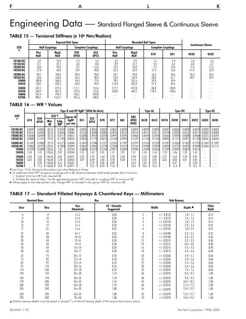
Engineering Data — Standard Flanged Sleeve & Continuous Sleeve<br />
TABLE 15 — Torsional Stiffness (x 10 6 Nm/Radian)<br />
SIZE<br />
<br />
Flex<br />
Half<br />
Exposed Bolt Types<br />
Shrouded Bolt Types<br />
Half Couplings Complete Couplings Half Couplings Complete Couplings<br />
Rigid<br />
Half<br />
G20<br />
GP20<br />
G52<br />
GP52<br />
Flex<br />
Half<br />
Rigid<br />
Half<br />
Continuous Sleeve<br />
G10 G51 GC02 GC05<br />
1010G/GC 4,7 10,3 2,4 3,2 3,2 9,5 1,6 2,4 3,3 3,2<br />
1015G/GC 12,1 24,1 6,0 8,0 8,9 21,2 4,4 6,2 6,8 6,7<br />
1020G/GC 18,3 39,4 9,2 12,4 14,5 35,8 7,2 10,3 11,6 11,5<br />
1025G/GC 27,8 69,0 13,9 20,0 22,3 62,9 11,2 16,5 21,9 22,0<br />
1030G/GC 40,1 103,0 20,0 28,8 33,1 95,8 16,5 24,6 34,3 34,6<br />
1035G/GC 53,0 169,6 26,4 40,3 56,0 154,9 28,0 41,1 48,9 49,9<br />
1040G 108,8 268,5 54,3 77,4 78,9 241,6 39,4 59,4 . . . . . .<br />
1045G 138,2 355,2 69,0 99,4 114,9 332,4 57,4 85,4 . . . . . .<br />
1050G 222,1 477,5 111,1 151,6 177,7 457,8 88,8 128,0 . . . . . .<br />
1055G 244,9 607,3 122,4 175,6 220,8 564,3 <strong>110</strong>,4 158,6 . . . . . .<br />
1060G 292,4 743,9 146,2 209,8 . . . . . . . . . . . . . . . . . .<br />
1070G 483,1 1152,7 241,6 340,4 . . . . . . . . . . . . . . . . . .<br />
TABLE 16 — WR 2 Values<br />
SIZE<br />
<br />
G10<br />
G20<br />
GP20<br />
Min.<br />
BE<br />
G32 <br />
Cplg.<br />
WR 2<br />
Type G and GP KgM 2 (With No Bore) Type GL Type GV Type GC<br />
Spacer <br />
KgM 2<br />
per mm<br />
G51<br />
G52<br />
GP52<br />
G70 G72 G81<br />
G82<br />
GP82<br />
GV82<br />
GL20 GL52 GV10 GV20 GV51 GV52 GC02 GC05<br />
1010G/GC 0,0047 0,0056 82,55 0,0102 0,0004 0,0050 0,0059 0,0032 0,0061 0,0050 0,0059 0,0059 0,0059 0,0047 0,0056 0,0050 0,0059 0,0030 0,0030<br />
1015G/GC 0,0161 0,0205 82,55 0,0366 0,0005 0,0164 0,0208 0,0085 0,0225 0,0167 0,0214 0,0211 0,0211 0,0158 0,0202 0,0167 0,0211 0,0085 0,0088<br />
1020G/GC 0,0360 0,0439 82,55 0,0717 0,0012 0,0380 0,0454 0,0234 0,0497 0,0395 0,0468 0,0454 0,0454 0,0366 0,0424 0,0380 0,0468 0,0225 0,0234<br />
1025G/GC 0,0884 0,1127 95,25 0,1785 0,0023 0,0936 0,1170 0,0614 0,1244 0,0995 0,1229 0,1156 0,1185 0,0892 0,1127 0,0951 0,1185 0,0644 0,0658<br />
1030G/GC 0,1697 0,2063 95,25 0,3175 0,0034 0,1814 0,2180 0,1317 0,2341 0,1931 0,2297 0,2165 0,2224 0,1697 0,2063 0,1829 0,2195 0,1369 0,1399<br />
1035G/GC 0,3862 0,4755 120,65 0,7300 0,0078 0,4067 0,4960 0,2750 0,5208 0,4213 0,5164 0,4930 0,5033 0,3833 0,4725 0,4053 0,4989 0,2663 0,2712<br />
1040G 0,7593 0,9085 120,65 1,32 0,0144 0,8003 0,9510 0,5764 0,9817 0,8339 0,9948 0,9539 0,9656 0,7549 0,9041 0,8047 0,9612 . . . . . .<br />
1045G 1,24 1,47 120,65 2,07 0,0258 1,31 1,52 1,01 1,51 1,37 1,57 1,54 1,54 1,23 1,46 1,32 1,53 . . . . . .<br />
1050G 2,20 2,63 146,05 3,87 0,0351 2,35 2,79 1,64 2,78 2,50 2,94 2,76 2,83 2,21 2,64 2,39 2,82 . . . . . .<br />
1055G 3,65 4,03 146,05 5,78 0,0465 3,97 4,39 2,40 4,18 4,28 4,74 4,23 4,45 3,65 4,04 4,01 4,44 . . . . . .<br />
1060G . . . 5,33 146,05 6,61 0,0661 . . . 5,79 3,96 6,09 . . . 6,25 5,69 5,91 . . . 5,37 . . . 5,90 . . . . . .<br />
1070G . . . 11,3 146,05 14,8 0,0971 . . . 12,3 8,29 11,8 . . . 13,3 12,0 12,5 . . . 11,4 . . . 12,5 . . . . . .<br />
See Page 13 for General <strong>Information</strong> and other Reference Notes.<br />
To determine total WR 2 of spacer couplings with a BE (distance between shaft ends) greater than minimum:<br />
1. Subtract minimum BE from required BE.<br />
2. Multiply the result of Step 1 by the appropriate spacer WR 2 and add to coupling WR 2 at minimum BE.<br />
Values apply to the tube portion only. Flange WR 2 is included in the spacer WR 2 for minimum BE.<br />
TABLE 17 — Standard Filleted Keyways & Chamfered Keys — Millimeters<br />
Over<br />
Nominal Bore Key Hub Keyway<br />
Thru<br />
Size<br />
(Nominal)<br />
45 ° Chamfer<br />
Suggested<br />
Width Depth Fillet<br />
Radii<br />
6 8 2 x 2 0,20 2 +/– 0,0125 1,0 / 1,1 0,16<br />
8 10 3 x 3 0,20 3 +/– 0,0125 1,4 / 1,5 0,16<br />
10 12 4 x 4 0,20 4 +/–0,0150 1,8 / 1,9 0,16<br />
12 17 5 x 5 0,32 5 +/–0,0150 2,3 / 2,4 0,25<br />
17 22 6 x 6 0,32 6 +/–0,0150 2,8 / 2,9 0,25<br />
22 30 8 x 7 0,32 8 +/–0,0180 3,3 / 3,5 0,25<br />
30 38 10 x 8 0,50 10 +/–0,0180 3,3 / 3,5 0,40<br />
38 44 12 x 8 0,50 12 +/–0,0215 3,5 / 3,5 0,40<br />
44 50 14 x 9 0,50 14 +/–0,0215 3,8 / 4,0 0,40<br />
50 58 16 x 10 0,50 16 +/–0,0215 4,3 / 4,5 0,40<br />
58 65 18 x 11 0,50 18 +/–0,0215 4,4 / 4,6 0,40<br />
65 75 20 x 12 0,70 20 +/–0,0260 4,9 / 5,1 0,60<br />
75 85 22 x 14 0,70 22 +/–0,0260 5,4 / 5,6 0,60<br />
85 95 25 x 14 0,70 25 +/–0,0260 5,4 / 5,6 0,60<br />
95 <strong>110</strong> 28 x 16 0,70 28 +/–0,0260 6,4 / 6,6 0,60<br />
<strong>110</strong> 130 32 x 18 0,70 32 +/–0,0310 7,4 / 7,6 0,60<br />
130 150 36 x 20 1,10 36 +/–0,0310 8,4 / 8,7 1,00<br />
150 170 40 x 22 1,10 40 +/–0,0310 9,4 / 9,7 1,00<br />
170 200 45 x 25 1,10 45 +/–0,0310 10,4 / 10,7 1,00<br />
200 230 50 x 28 1,10 50 +/–0,0310 11,4 / 11,7 1,00<br />
230 260 56 x 32 1,80 56 +/–0,0370 12,4 / 12,7 1,60<br />
260 290 63 x 32 1,80 63 +/–0,0370 12,4 / 12,7 1,60<br />
290 330 70 x 36 1,80 70 +/–0,0370 14,4 / 14,7 1,60<br />
Shallow keyway depths must be equal or exceed 2 / 3 of the full keyway depth of the square keys shown above.<br />
38 (<strong>M451</strong>-<strong>110</strong>) The Falk Corporation, 1998, <strong>2002</strong>.