Basic Information Selection Guide M451-110, August 2002 - Rexnord
Basic Information Selection Guide M451-110, August 2002 - Rexnord
Basic Information Selection Guide M451-110, August 2002 - Rexnord

Create successful ePaper yourself
Turn your PDF publications into a flip-book with our unique Google optimized e-Paper software.
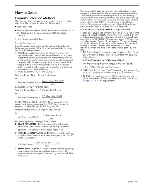
How to Select<br />
Formula <strong>Selection</strong> Method<br />
The Standard <strong>Selection</strong> Method can be used for most coupling<br />
selections. The procedure below should be used for:<br />
High Peak Loads<br />
Brake Applications (where the disc brake or brakewheel is to be<br />
an integral part of the coupling, consult Falk for design<br />
options.)<br />
High Frequency Axial Sliding<br />
Shear Pin Couplings<br />
Providing system peak torque and frequency, duty cycle, and<br />
brake torque rating will allow for a more refined selection using<br />
the Formula <strong>Selection</strong> Method.<br />
1. High Peak Loads: Use one of the following formulas for<br />
applications using motors, with torque characteristics that are<br />
higher than normal; applications with intermittent operations,<br />
shock loading, inertia effects due to starting and stopping and<br />
or system induced repetitive high peak torques. System Peak<br />
Torque is the maximum torque that can exist in the system.<br />
Select a coupling with a torque rating equal to or greater than<br />
selection torque calculated below.<br />
A. NON-REVERSING HIGH PEAK TORQUE<br />
<strong>Selection</strong> Torque (Nm) = System Peak Torque<br />
or<br />
System Peak kW x 9549<br />
<strong>Selection</strong> Torque (Nm) =<br />
rpm<br />
B. REVERSING HIGH PEAK TORQUE<br />
<strong>Selection</strong> Torque (Nm) = 1.5 x System Peak Torque<br />
or<br />
1.5 x Peak kW x 9549<br />
<strong>Selection</strong> Torque (Nm) =<br />
rpm<br />
C. OCCASIONAL PEAK TORQUES (Non-Reversing) — If a<br />
system peak torque occurs less than 1000 times during the<br />
expected coupling life, use the following formula:<br />
<strong>Selection</strong> Torque (Nm) = .5 x System Peak Torque<br />
or<br />
.5 x Peak kW x 9549<br />
<strong>Selection</strong> Torque (Nm) =<br />
rpm<br />
For reversing service, select per Step B, above.<br />
2. BRAKE APPLICATIONS: If the torque rating of the brake<br />
exceeds the motor torque, use the brake rating as follows:<br />
<strong>Selection</strong> Torque (Nm) = Brake Torque Rating x S.F.<br />
3. HIGH FREQUENCY AXIAL SLIDING: For Type GL couplings;<br />
if axial movement occurs more than 5 times per hour, add .25<br />
to the service factor.<br />
The user provided shear torque value must be based on a system<br />
analysis. It is recommended that the shear torque value be at least<br />
225% of the normal transmitted torque value for non-reversing<br />
applications to avoid breaking the shear pins due to fatigue during<br />
motor start-up. For reversing applications, the recommended shear<br />
torque setting is 300-400% of normal torque to avoid fatigue<br />
failures. If the connected equipment cannot tolerate these torque<br />
levels, expect to replace the shear pins more frequently.<br />
FORMULA SELECTION EXAMPLE — High Peak Load:<br />
Select a gear coupling to connect a gear drive low speed shaft to<br />
a reversing runout mill table. The electric motor rating is 37 kW<br />
at its base speed and the system peak torque at the coupling is<br />
estimated to be 17 000 Nm The coupling speed is 77 rpm at the<br />
motor base speed. Drive shaft diameter is 100 mm and keyway<br />
is 28 mm x 16 mm. Runout table roll diameter is 135 mm and<br />
keyway is 36 mm x 20 mm. Shaft separation is 12 mm<br />
maximum. Motor and drive shaft extensions are both 180 mm<br />
long.<br />
1. TYPE: From Page 7, to connect close coupled shafts (12 mm<br />
gap), the double engagement Type G20 Steel Mill coupling<br />
is the selection.<br />
2. REQUIRED MINIMUM COUPLING RATING:<br />
Use the Reversing High Peak Torque formula in Step 1B.<br />
1.5 x 17 000= 25 500 <strong>Selection</strong> Torque<br />
3. SIZE: From Table 1, Size 1040G20 coupling with torque rating<br />
of 30 600 exceeds the selection torque of 25 500 Nm<br />
4. CHECK: The maximum bore of 160 mm with square key,<br />
allowable speed of 3600 rpm and Dimension M of 145 mm,<br />
on Page 17, meet the requirements.<br />
kW x 9549 x (S.F. + .25)<br />
<strong>Selection</strong> Torque<br />
rpm<br />
4. SHEAR PIN COUPLINGS: When selecting Type GR couplings,<br />
make certain that the required shear torque is within the<br />
minimum/maximum range for the coupling size selected. Refer<br />
to Page 33.<br />
The Falk Corporation, 1998, <strong>2002</strong>. (<strong>M451</strong>-<strong>110</strong>) 11