Basic Information Selection Guide M451-110, August 2002 - Rexnord
Basic Information Selection Guide M451-110, August 2002 - Rexnord
Basic Information Selection Guide M451-110, August 2002 - Rexnord

Create successful ePaper yourself
Turn your PDF publications into a flip-book with our unique Google optimized e-Paper software.
F A L K<br />
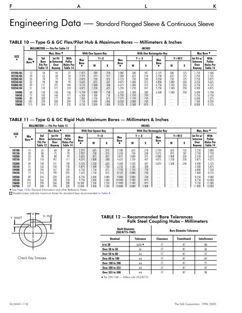
Engineering Data — Standard Flanged Sleeve & Continuous Sleeve<br />
TABLE10—TypeG&GCFlex/Pilot Hub & Maximum Bores — Millimeters & Inches<br />
SIZE<br />
<br />
MILLIMETERS — Fits Per Table 12<br />
Max. Bore With One Square Key With One Rectangular Key Max Bore <br />
Min Std Int Fit With<br />
Bore Max<br />
Y=X<br />
Y=X<br />
Y=W/2 Int Fit w/ With<br />
Bore w/Setscrew Puller<br />
Max<br />
Max<br />
Bore<br />
Setscrew Puller<br />
Fits Per Over Holes Per<br />
Bore<br />
Bore<br />
W X W X W X Over Holes Per<br />
Table 12 Keyway Table 14<br />
Keyway Table 14<br />
1010G/GC 13 50 45 37 1.875 .500 .250 2.000 .500 .187 2.125 .500 .125 1.750 1.500<br />
1015G/GC 20 65 60 54 2.375 .625 .312 2.500 .625 .218 2.750 .625 .125 2.250 2.125<br />
1020G/GC 26 78 75 72 2.875 .750 .375 3.125 .750 .250 3.250 .750 .125 2.750 2.875<br />
1025G/GC 32 98 88 92 3.625 .875 .437 3.875 1.000 .375 4.000 1.000 .250 3.250 3.625<br />
1030G/GC 39 111 101 104 4.125 1.000 .500 4.375 1.000 .375 4.750 1.250 .250 3.750 4.125<br />
1035G/GC 51 134 121 124 4.875 1.250 .625 5.250 1.250 .437 5.750 1.500 .250 4.500 4.875<br />
1040G 64 160 150 146 5.750 1.500 .750 6.250 1.500 .500 6.500 1.500 .250 5.500 5.750<br />
1045G 77 183 160 171 6.500 1.500 .750 6.750 1.750 .750 . . . . . . . . . 5.750 6.750<br />
1050G 89 200 177 187 7.000 1.750 .875 7.375 1.750 .750 . . . . . . . . . 6.500 7.375<br />
1055G 102 220 200 209 7.750 2.000 1.000 8.250 2.000 .750 . . . . . . . . . 7.500 8.250<br />
1060G 115 244 212 232 8.750 2.000 1.000 9.125 2.500 .875 . . . . . . . . . 8.000 9.125<br />
INCHES<br />
TABLE11—TypeG&GCRigidHubMaximum Bores — Millimeters & Inches<br />
SIZE<br />
<br />
MILLIMETERS — Fits Per Table 12<br />
Max Bore With One Square Key With One Rectangular Key Max. Bore <br />
Min Std Int Fit With<br />
Bore Max<br />
Y=X<br />
Y=X<br />
Y=W/2 Int Fit w/ With<br />
Max<br />
Max<br />
Bore w/Setscrew Puller<br />
Bore<br />
Setscrew Puller<br />
Bore<br />
Bore<br />
Fits Per Over Holes Per W X W X W X Over Holes Per<br />
Table 12 Keyway Table 14<br />
Keyway Table 14<br />
1010G 13 65 60 50 2.375 .625 .312 2.500 .625 .218 2.750 .625 .125 2.250 2.000<br />
1015G 20 80 75 70 2.937 .750 .375 3.250 .750 .250 3.375 .875 .187 2.750 2.750<br />
1020G 26 98 88 92 3.625 .875 .437 3.875 1.000 .375 4.000 1.000 .250 3.250 3.625<br />
1025G 32 118 107 111 4.375 1.000 .500 4.625 1.250 .437 4.875 1.250 .250 3.875 4.375<br />
1030G 39 140 121 130 5.125 1.250 .625 5.500 1.250 .437 5.875 1.500 .250 4.500 5.125<br />
1035G 51 163 150 150 5.875 1.500 .750 6.250 1.500 .500 . . . . . . . . . 5.500 5.875<br />
1040G 64 196 167 185 6.750 1.750 .875 7.250 1.750 .750 . . . . . . . . . 6.000 7.250<br />
1045G 77 216 190 205 7.625 1.750 .875 8.125 2.000 .750 . . . . . . . . . 7.000 8.125<br />
1050G 89 235 220 228 8.750 2.000 1.000 9.000 2.000 .750 . . . . . . . . . 8.250 9.000<br />
1055G 102 266 230 250 9.750 2.000 1.000 10.000 2.500 .875 . . . . . . . . . 8.750 10.000<br />
1060G 115 290 260 280 10.500 2.500 1.250 11.000 2.500 .875 . . . . . . . . . 9.750 11.000<br />
1070G 127 340 290 330 12.000 3.000 1.500 13.000 3.000 1.000 . . . . . . . . . 11.000 13.000<br />
See Page 13 for General <strong>Information</strong> and other Reference Notes.<br />
Shaded areas indicate maximum bores for standard keys recommended in Table 8.<br />
INCHES<br />
Y-SHAFT<br />
W<br />
X-HUB<br />
TABLE 12 — Recommended Bore Tolerances<br />
Falk Steel Coupling Hubs – Millimeters<br />
Shaft Diameter<br />
(ISO/R775-1969)<br />
Bore Diameter Tolerance<br />
Check Key Stresses<br />
Nominal Tolerance Clearance Transitional Interference<br />
6to30 j6/k6 F7 H7 M6<br />
Over 30 to 50 k6 F7 H7 K6<br />
Over 50 to 80 m6 F7 H7 K7<br />
Over 80 to 100 m6 F7 H7 M7<br />
Over 100 to 200 m6 F7 H7 P7<br />
Over 200 to 355 m6 F7 H7 R7<br />
Over 355 to 500 m6 F7 H7 R8<br />
Per DIN 748 — Differs with ISO/R775.<br />
36 (<strong>M451</strong>-<strong>110</strong>) The Falk Corporation, 1998, <strong>2002</strong>.