Basic Information Selection Guide M451-110, August 2002 - Rexnord
Basic Information Selection Guide M451-110, August 2002 - Rexnord
Basic Information Selection Guide M451-110, August 2002 - Rexnord

Create successful ePaper yourself
Turn your PDF publications into a flip-book with our unique Google optimized e-Paper software.
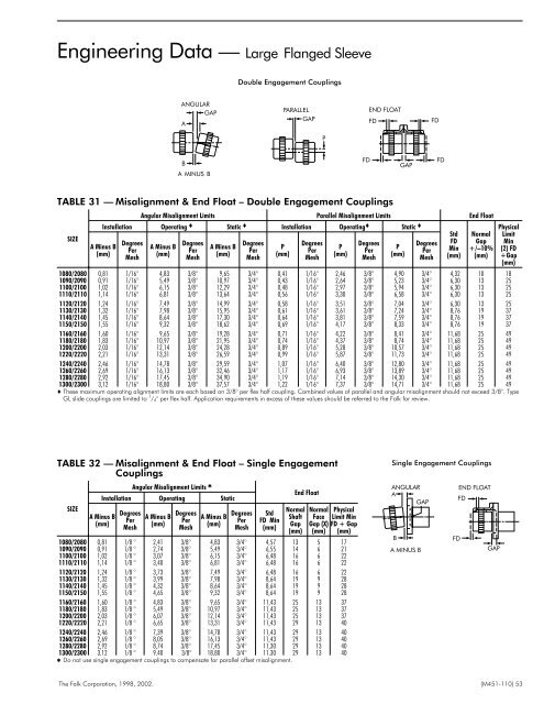
Engineering Data — Large Flanged Sleeve<br />
Double Engagement Couplings<br />
ANGULAR<br />
GAP<br />
A<br />
PARALLEL<br />
GAP<br />
END FLOAT<br />
FD<br />
FD<br />
P<br />
B<br />
A MINUS B<br />
FD<br />
GAP<br />
FD<br />
TABLE 31 — Misalignment & End Float – Double Engagement Couplings<br />
SIZE<br />
Angular Misalignment Limits Parallel Misalignment Limits End Float<br />
Installation Operating Static Installation Operating Static Std Normal<br />
Degrees<br />
Degrees<br />
Degrees<br />
Degrees<br />
Degrees<br />
Degrees FD Gap<br />
A Minus B<br />
A Minus B<br />
A Minus B<br />
P<br />
P<br />
P<br />
Per<br />
Per<br />
Per<br />
Per<br />
Per<br />
Per Min +/–10%<br />
(mm)<br />
(mm)<br />
(mm)<br />
(mm)<br />
(mm)<br />
(mm)<br />
Mesh<br />
Mesh<br />
Mesh<br />
Mesh<br />
Mesh<br />
Mesh (mm) (mm)<br />
1080/2080 0,81 1/16° 4,83 3/8° 9,65 3/4° 0,41 1/16° 2,46 3/8° 4,90 3/4° 4,32 10 18<br />
1090/2090 0,91 1/16° 5,49 3/8° 10,97 3/4° 0,43 1/16° 2,64 3/8° 5,23 3/4° 6,30 13 25<br />
<strong>110</strong>0/2100 1,02 1/16° 6,15 3/8° 12,29 3/4° 0,48 1/16° 2,97 3/8° 5,94 3/4° 6,30 13 25<br />
1<strong>110</strong>/2<strong>110</strong> 1,14 1/16° 6,81 3/8° 13,64 3/4° 0,56 1/16° 3,30 3/8° 6,58 3/4° 6,30 13 25<br />
1120/2120 1,24 1/16° 7,49 3/8° 14,99 3/4° 0,58 1/16° 3,51 3/8° 7,04 3/4° 6,30 13 25<br />
1130/2130 1,32 1/16° 7,98 3/8° 15,95 3/4° 0,61 1/16° 3,61 3/8° 7,24 3/4° 8,76 19 37<br />
1140/2140 1,45 1/16° 8,64 3/8° 17,30 3/4° 0,64 1/16° 3,81 3/8° 7,59 3/4° 8,76 19 37<br />
1150/2150 1,55 1/16° 9,32 3/8° 18,62 3/4° 0,69 1/16° 4,17 3/8° 8,33 3/4° 8,76 19 37<br />
1160/2160 1,60 1/16° 9,65 3/8° 19,28 3/4° 0,71 1/16° 4,22 3/8° 8,41 3/4° 11,68 25 49<br />
1180/2180 1,83 1/16° 10,97 3/8° 21,95 3/4° 0,74 1/16° 4,37 3/8° 8,74 3/4° 11,68 25 49<br />
1200/2200 2,03 1/16° 12,14 3/8° 24,28 3/4° 0,89 1/16° 5,28 3/8° 10,57 3/4° 11,68 25 49<br />
1220/2220 2,21 1/16° 13,31 3/8° 26,59 3/4° 0,99 1/16° 5,87 3/8° 11,73 3/4° 11,68 25 49<br />
1240/2240 2,46 1/16° 14,78 3/8° 29,59 3/4° 1,07 1/16° 6,40 3/8° 12,80 3/4° 11,68 25 49<br />
1260/2260 2,69 1/16° 16,13 3/8° 32,46 3/4° 1,17 1/16° 6,93 3/8° 13,89 3/4° 11,68 25 49<br />
1280/2280 2,92 1/16° 17,45 3/8° 34,90 3/4° 1,19 1/16° 7,14 3/8° 14,30 3/4° 11,68 25 49<br />
1300/2300 3,12 1/16° 18,80 3/8° 37,57 3/4° 1,22 1/16° 7,37 3/8° 14,71 3/4° 11,68 25 49<br />
These maximum operating alignment limits are each based on 3/8° per flex half coupling. Combined values of parallel and angular misalignment should not exceed 3/8°. Type<br />
GL slide couplings are limited to 1 / 4° per flex half. Application requirements in excess of these values should be referred to the Falk for review.<br />
Physical<br />
Limit<br />
Min<br />
(2) FD<br />
+Gap<br />
(mm)<br />
TABLE 32 — Misalignment & End Float – Single Engagement<br />
Couplings<br />
SIZE<br />
Angular Misalignment Limits <br />
Installation Operating Static<br />
A Minus B<br />
(mm)<br />
Degrees<br />
Per<br />
Mesh<br />
A Minus B<br />
(mm)<br />
Degrees<br />
Per<br />
Mesh<br />
A Minus B<br />
(mm)<br />
Degrees<br />
Per<br />
Mesh<br />
Std<br />
FD Min<br />
(mm)<br />
End Float<br />
Normal<br />
Shaft<br />
Gap<br />
(mm)<br />
Normal Physical<br />
Face Limit Min<br />
Gap (X) FD + Gap<br />
(mm) (mm)<br />
1080/2080 0,81 1/8 ° 2,41 3/8° 4,83 3/4° 4,57 13 5 17<br />
1090/2090 0,91 1/8 ° 2,74 3/8° 5,49 3/4° 6,55 14 6 21<br />
<strong>110</strong>0/2100 1,02 1/8 ° 3,07 3/8° 6,15 3/4° 6,48 16 6 22<br />
1<strong>110</strong>/2<strong>110</strong> 1,14 1/8 ° 3,40 3/8° 6,81 3/4° 6,48 16 6 22<br />
1120/2120 1,24 1/8 ° 3,73 3/8° 7,49 3/4° 6,48 16 6 22<br />
1130/2130 1,32 1/8 ° 3,99 3/8° 7,98 3/4° 8,64 19 9 28<br />
1140/2140 1,45 1/8 ° 4,32 3/8° 8,64 3/4° 8,64 19 9 28<br />
1150/2150 1,55 1/8 ° 4,65 3/8° 9,32 3/4° 8,64 19 9 28<br />
1160/2160 1,60 1/8 ° 4,83 3/8° 9,65 3/4° 11,43 25 13 37<br />
1180/2180 1,83 1/8 ° 5,49 3/8° 10,97 3/4° 11,43 25 13 37<br />
1200/2200 2,03 1/8 ° 6,07 3/8° 12,14 3/4° 11,43 25 13 37<br />
1220/2220 2,21 1/8 ° 6,65 3/8° 13,31 3/4° 11,43 29 13 40<br />
1240/2240 2,46 1/8 ° 7,39 3/8° 14,78 3/4° 11,43 29 13 40<br />
1260/2260 2,69 1/8 ° 8,05 3/8° 16,13 3/4° 11,43 29 13 40<br />
1280/2280 2,92 1/8 ° 8,74 3/8° 17,45 3/4° 11,30 29 13 40<br />
1300/2300 3,12 1/8 ° 9,40 3/8° 18,80 3/4° 11,30 29 13 40<br />
Do not use single engagement couplings to compensate for parallel offset misalignment.<br />
Single Engagement Couplings<br />
ANGULAR<br />
END FLOAT<br />
A<br />
FD<br />
GAP<br />
B<br />
FD<br />
A MINUS B<br />
GAP<br />
The Falk Corporation, 1998, <strong>2002</strong>. (<strong>M451</strong>-<strong>110</strong>) 53