Basic Information Selection Guide M451-110, August 2002 - Rexnord
Basic Information Selection Guide M451-110, August 2002 - Rexnord
Basic Information Selection Guide M451-110, August 2002 - Rexnord

Create successful ePaper yourself
Turn your PDF publications into a flip-book with our unique Google optimized e-Paper software.
F A L K<br />
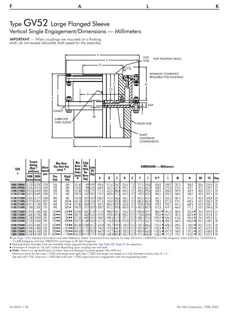
Type GV52 Large Flanged Sleeve<br />
Vertical Single Engagement/Dimensions — Millimeters<br />
IMPORTANT — When couplings are mounted on a floating<br />
shaft, do not exceed allowable shaft speed for the assembly,<br />
A<br />
D<br />
F<br />
FLEX<br />
HUB<br />
(TOP POSITION ONLY)<br />
MINIMUM CLEARANCE<br />
REQUIRED FOR ALIGNING<br />
C<br />
M<br />
B<br />
J<br />
N<br />
CS<br />
GAP<br />
GASKET<br />
LUBRICATE<br />
THRU SLEEVE<br />
BE<br />
L<br />
E<br />
RIGID HUB<br />
K<br />
SHAFT<br />
CENTERING<br />
COMPONENTS<br />
SIZE<br />
<br />
Torque<br />
Rating<br />
(Nm) †<br />
(millions)<br />
1000 2000<br />
Series Series<br />
Allow<br />
Speed<br />
rpm<br />
Max Bore<br />
One Rect Key<br />
(mm) <br />
Flex<br />
Hub<br />
Rigid<br />
Hub<br />
Min<br />
Bore<br />
Both<br />
Hubs<br />
(mm)<br />
<br />
Cplg<br />
Wt.<br />
With<br />
No<br />
Bore<br />
(kg)<br />
Lube<br />
Wt<br />
(kg)<br />
DIMENSIONS — Millimeters<br />
A B C D E F J K L M N BE CS Gap<br />
1080/2080G 0,170 0,234 1750 266 340 101,60 699 4,99 590,6 511,6 236,7 355,6 7,9 571,5 242,8 450,8 248,9 287,3 368,3 38,6 224,0 26<br />
1090/2090G 0,226 0,315 1550 290 380 114,30 984 6,35 660,4 567,2 261,9 393,7 7,9 641,4 265,2 508,0 275,8 314,5 419,1 42,2 249,2 29<br />
<strong>110</strong>0/2100G 0,310 0,443 1450 320 400 127,00 1252 7,71 711,2 625,3 288,8 444,5 9,7 698,5 293,6 530,4 304,8 339,9 469,9 48,3 273,1 33<br />
1<strong>110</strong>/2<strong>110</strong>G 0,413 0,609 1330 373 440 139,70 1637 9,07 774,7 682,8 317,2 495,3 9,7 749,3 322,3 584,2 333,2 368,3 520,7 48,3 301,5 33<br />
1120/2120G 0,555 0,777 1200 400 483 152,40 2077 10,9 838,2 721,4 336,6 546,1 9,7 825,5 341,4 647,7 352,3 387,4 571,5 48,3 320,8 33<br />
1130/2130G 0,719 0,925 1075 440 500 165,10 2572 16,8 911,4 762,0 352,0 584,2 9,7 886,0 362,0 708,2 371,3 419,1 609,6 54,9 336,3 39<br />
1140/2140G 0,911 1,140 920 460 535 177,80 3062 17,2 965,2 806,4 373,9 635,0 9,7 939,8 378,0 749,3 393,7 441,5 660,4 54,9 358,1 39<br />
1150/2150G 1,100 1,350 770 490 580 190,50 3751 20,9 1 028,7 857,2 399,8 685,8 9,7 1 003,3 407,9 812,8 419,1 466,9 711,2 54,9 384,0 39<br />
1160/2160G 1,310 1,640 650 525 630 254,00 4631 21,8 1 111,2 908,0 416,1 736,6 12,7 1 085,8 419,1 886,0 441,5 482,6 762,0 70,4 397,0 51<br />
1180/2180G 1,660 2,140 480 600 710 285,75 6069 25,4 1 219,2 939,8 431,8 838,2 12,7 1 193,8 434,8 993,6 457,2 501,6 863,6 70,4 412,8 51<br />
1200/2200G 2,140 2,850 370 660 780 317,50 8482 34,5 1 358,9 1 098,6 511,0 927,1 12,7 1 308,1 514,4 1 095,2 536,4 616,0 965,2 70,4 492,3 51<br />
1220/2220G 2,720 3,560 290 725 890 349,25 11 680 54,4 1 511,3 1 196,8 555,8 1 016,0 15,7 1 473,2 565,2 1 244,6 584,2 660,4 1 066,8 83,3 530,4 58<br />
1240/2240G 3,470 4,480 270 810 940 381,00 14 388 56,7 1 632,0 1 285,7 599,9 1 130,3 15,7 1 581,2 606,6 1 314,7 628,6 698,5 1 168,4 83,3 574,5 58<br />
1260/2260G 4,490 5,480 250 880 1 015 412,75 17 722 61,2 1 746,2 1 374,6 644,7 1 231,9 15,7 1 695,4 647,7 1 422,4 673,1 749,3 1 270,0 83,1 619,3 58<br />
1280/2280G 5,840 6,760 230 950 1 090 444,50 21 <strong>110</strong> 70,3 1 866,9 1 412,7 663,4 1 333,5 15,7 1 803,4 666,8 1 530,6 691,9 768,4 1 371,6 83,1 638,0 58<br />
1300/2300G 6,760 8,190 220 1 025 1 170 476,25 24 712 77,1 1 974,8 1 450,8 682,8 1 435,1 15,7 1 911,4 685,8 1 638,3 711,2 774,7 1 473,2 83,1 657,4 58<br />
See Page 13 for General <strong>Information</strong> and other Reference Notes. Downward thrust capacity for Sizes 1010 thru 1030GV52 is 4 536 kilograms; Sizes 1035 thru 1070GV52 is<br />
13 608 kilograms and Size 1080GV52 and larger is 39 463 kilograms.<br />
Reduced shank diameter hubs are available where required bore permits. See Table 28, Page 51 for selections.<br />
Dimension K maybe an “as cast” surface depending upon coupling size and bore.<br />
Note: There is no standardization of metric keys and keyways for bores greater than 500 mm.<br />
Maximum bores for flex hubs 1150G and larger and rigid hubs 1130G and larger are based on a hub diameter to bore ratio of 1.4.<br />
See also 457-130. Sizes thru 1140G flex hubs and 1120G rigid hubs are in agreement with that engineering sheet.<br />
44 (<strong>M451</strong>-<strong>110</strong>) The Falk Corporation, 1998, <strong>2002</strong>.