F A L K Type G52 Standard Flanged Sleeve Floating Shafts/Dimensions — Millimeters A standard floating shaft assembly consists of two standard single engagement couplings, two gap discs and a connecting shaft. A floating shaft can eliminate the need for additional bearing supports along spanning shaft because the shaft is supported at the ends by connected equipment through the single engagement couplings. Flex Hubs on Floating Shaft (RFFR) Assembly of the flex hubs on the floating shaft allows for easier replacement in case of wear and allows the rigid hubs with their increased bore capacity to be used on the connected equipment shafts. This frequently means a smaller coupling size can be utilized. Rigid Hubs on Floating Shaft (FRRF) When the rigid hubs are on the floating shaft, shorter shaft spans can be accommodated, since no cover drawback is required. Since the flex hubs are outboard, the points of articulation are further apart, providing greater offset misalignment capacity. Solid Floating Shaft <strong>Selection</strong> Single Engagement Type G52/GV52 couplings are used with floating shafts in either horizontal or vertical applications. For vertical applications select a Type GV coupling for the lower coupling assembly. Select floating shafts as follows: 1. Use the Standard or Formula <strong>Selection</strong> Methods, Pages 10-11 to select the couplings. Record the System Torque from standard selection method or <strong>Selection</strong> Torque from formula selection method. OPERATING SPEED – RPM 2000 1500 1000 500 BALANCING NORMALLY NOT REQUIRED BALANCING OF SHAFT REQUIRED 254 508 762 1016 1270 1524 1778 2032 DISTANCE BETWEEN SHAFT ENDS – MILLIMETERS 2. From table below select a shaft diameter that has an assembly torque rating equal to or greater than the system or selection torque determined in coupling selection. 3. Check maximum “BE” for the shaft diameter selected and running speed for shaft length required from table below. Refer to graph at left to determine if shaft requires balancing. 4. If the application shaft length exceeds the maximum “BE” listed, select the next larger shaft diameter or the next larger size coupling. Consult Falk for higher speeds or longer shaft lengths than listed below. NOTE: For conditions that require a larger size coupling, consider a Tubular Shaft Design, refer complete application details to your local Falk Representative. SIZE 1010G 1015G 1020G 1025G 1030G 1035G 1040G 1045G 1050G 1055G 1060G 1070G Assembly Torque Rating Nm † SB Shaft End Diameter (mm) SD Shaft Diameter (mm) Wt-kg per mm WR 2 kgm 2 per mm Floating Shafts — Millimeters Maximum BE (mm) for Various RPM’s 1750 1430 1170 870 720 580 493 38,1 39,7 0,00964 0,00000196 1 371 1 524 1 676 1 955 2 159 2 387 2 463 1 139 47,6 50,8 0,0159 0,00000518 1 549 1 727 1 905 2 209 2 438 2 717 2 794 1 169 50,8 54,0 0,0179 0,00000657 1 600 1 778 1 955 2 286 2 514 2 794 2 870 2 349 60,3 76,2 0,0248 0,0000126 1 752 1 930 2 133 2 463 2 717 3 022 3 124 2 282 63,5 66,7 0,0273 0,0000152 1 778 1 981 2 184 2 540 2 794 3 098 3 200 4 271 73,0 95,2 0,0557 0,0000259 1 905 2 108 2 336 2 717 2 971 3 327 3 429 4 463 79,4 82,6 0,0420 0,0000357 1 981 2 209 2 438 2 819 3 098 3 454 3 556 7 474 92,1 95,2 0,0559 0,0000634 2 133 2 362 2 616 3 022 3 237 3 708 3 835 8 508 98,4 101,6 0,0636 0,0000820 2 209 2 438 2 692 3 124 3 454 3 835 3 962 12 101 104,8 127,0 0,0718 0,000104 2 260 2 514 2 794 3 225 3 556 3 962 4 064 13 333 114,3 120,6 0,0896 0,000163 2 413 2 667 2 946 3 403 3 759 4 191 4 292 18 508 123,8 146,0 0,993 0,000200 2 463 2 717 3 022 3 505 3 860 4 292 4 419 24 327 139,7 146,0 0,131 0,000350 2 641 2 921 3 251 3 759 4 140 4 597 4 749 30 609 146,0 165,1 0,143 0,000415 2 692 2 997 3 302 3 835 4 216 4 699 4 851 31 581 152,4 165,1 0,168 0,000572 2 819 3 124 3 454 3 987 4 394 4 902 5 029 41 999 171,5 203,2 0,254 0,00131 3 124 3 454 3 810 4 445 4 876 5 435 5 588 37 886 161,9 165,1 0,168 0,000572 2 819 3 124 3 454 3 987 4 394 4 902 5 029 56 597 187,3 203,2 0,254 0,00131 3 124 3 454 3 810 4 445 4 876 5 435 5 588 37 886 161,9 165,1 0,168 0,000572 2 819 3 124 3 454 3 987 4 394 4 902 5 029 74 031 200,0 203,2 0,254 0,00131 3 124 3 454 3 810 4 445 4 876 5 435 5 588 71 410 200,0 203,2 0,254 0,00131 3 124 3 454 3 810 4 445 4 876 5 435 5 588 90 404 215,9 217,4 0,291 0,00172 3 225 3 581 3 962 4 597 5 054 5 613 5 791 71 410 200,0 203,2 0,254 0,00131 3 124 3 454 3 810 4 445 4 876 5 435 5 588 135 250 241,3 242,8 0,363 0,00268 3 403 3 784 4 191 4 851 5 334 5 943 6 121 Refer to Page 13 for General <strong>Information</strong> and Reference Notes. Assembly torque rating is limited by coupling size, shaft end diameter or both. Interpolate for intermediate speeds. Maximum BE is based on 70% of critical speed. Refer to the Falk for higher running speeds. 540 or less 20 (<strong>M451</strong>-<strong>110</strong>) The Falk Corporation, 1998, <strong>2002</strong>.
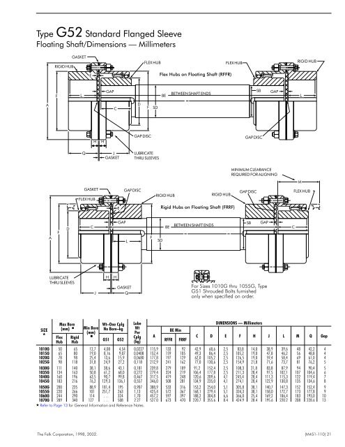
Type G52 Standard Flanged Sleeve Floating Shaft/Dimensions — Millimeters RIGID HUB GASKET FLEX HUB FLEX HUB RIGID HUB E Flex Hubs on Floating Shaft (RFFR) F L GAP BE BETWEEN SHAFT ENDS SB GAP L A C D F SD H H GAP DISC GAP DISC Q J GASKET LUBRICATE THRU SLEEVES MINIMUM CLEARANCE REQUIRED FOR ALIGNING M GASKET FLEX HUB GAP DISC RIGID HUB RIGID HUB GAP DISC FLEX HUB E Rigid Hubs on Floating Shaft (FRRF) A F D C GAP L F SD BE BETWEEN SHAFT ENDS SB GAP C LUBRICATE THRU SLEEVES J H H GASKET Q For Sizes 1010G thru 1055G, Type G51 Shrouded Bolts furnished only when specified on order. SIZE Flex Hub Max Bore (mm) Rigid Hub Min Bore (mm) Wt–One Cplg No Bore–kg Lube Wt Per Cplg (kg) BE Min A G51 G52 RFFR FRRF DIMENSIONS — Millimeters C D E F H J L M Q Gap 1010G 50 65 12,7 4,08 4,54 0,0227 115,9 133 92 42,9 68,6 2,5 83,8 14,0 38,9 39,6 48 42,2 4 1015G 65 80 19,0 8,16 9,07 0,0408 152,4 159 105 49,3 86,4 2,5 105,2 19,0 47,8 46,2 56 48,8 4 1020G 78 98 25,4 13,6 15,9 0,0680 177,8 197 129 62,0 105,2 2,5 126,5 19,0 59,4 58,4 69 61,0 4 1025G 98 118 31,8 24,9 27,2 0,118 212,9 241 162 77,0 130,6 2,5 154,9 21,8 71,6 73,7 81 76,2 5 1030G 111 140 38,1 38,6 43,1 0,181 239,8 279 189 91,2 152,4 2,5 108,3 21,8 83,8 87,9 94 90,4 5 1035G 134 163 50,8 61,2 68,0 0,272 279,4 324 219 106,4 177,8 2,5 211,3 28,4 97,5 102,1 107 104,6 6 1040G 160 196 63,5 90,7 99,8 0,467 317,5 419 248 120,6 209,6 4,1 245,4 28,4 111,3 115,3 122 119,4 7 1045G 183 216 76,2 129,3 136,1 0,557 346,0 508 281 134,9 235,0 4,1 274,1 28,4 122,9 130,8 135 134,6 8 1050G 200 235 88,9 181,4 195 0,907 388,9 533 316 153,2 254,0 5,1 305,8 38,1 140,7 147,3 152 152,4 9 1055G 220 266 101 251,7 263 1,13 425,4 572 367 168,1 279,4 5,1 334,3 38,1 158,0 172,7 173 177,8 9 1060G 244 290 114 . . . 324 1,70 457,2 597 397 188,2 304,8 6,6 366,0 25,4 169,2 186,4 183 193,0 10 1070G 289 340 127 . . . 508 2,27 527,0 673 470 220,7 355,6 8,4 424,9 28,4 195,6 220,2 208 228,6 13 Refer to Page 13 for General <strong>Information</strong> and Reference Notes. The Falk Corporation, 1998, <strong>2002</strong>. (<strong>M451</strong>-<strong>110</strong>) 21