NOVAR 1106 / 1114 / 1206 / 1214 NOVAR 1xxx / S400 NOVAR ...
NOVAR 1106 / 1114 / 1206 / 1214 NOVAR 1xxx / S400 NOVAR ...
NOVAR 1106 / 1114 / 1206 / 1214 NOVAR 1xxx / S400 NOVAR ...

Create successful ePaper yourself
Turn your PDF publications into a flip-book with our unique Google optimized e-Paper software.
<strong>NOVAR</strong> <strong>1xxx</strong> EPM Elektropřístroj s. r. o.<br />
If the parameter value is set to say 3.0 and the above mentioned conditions are met in the power<br />
system, the controller calculates optimum compensation and carries out control intervention every 3<br />
minutes.<br />
The time mentioned gets shorter in proportion to the instantaneous control deviation. If control time<br />
without preceding character ―L‖ is set, it gets shorter as square of control deviation over the smallest<br />
capacitive section value (C/k MIN). If the control time with preceding character ―L‖ is specified, it gets<br />
shorter in proportion to this ratio (―L‖ = Linear, causes slower response to large deviations). Rising<br />
control deviation can decrease this value to the minimum control time of 5 seconds.<br />
On the contrary, if the control deviation is smaller than the smallest capacitive section current (C/k MIN),<br />
control time gets twice as long. If the control deviation falls further under half of the smallest capacitive<br />
section current value (C/k MIN), no control interventions take place.<br />
4.1.4 Parameter 03/09 – Overcompensation Control Time<br />
The value for metering rate 1 (parameter 03) or for metering rate 2 (parameter 9) determines the<br />
frequency of control interventions, very much like in parameter 02/08 described above. There is<br />
a difference though: it only applies if the instantaneous power factor is more capacitive than that<br />
required, that is it is overcompensated.<br />
The control time operation in proportion to control deviation magnitude is the same as with parameter<br />
02/08 described above.<br />
4.1.5 Parameter 04/10 – Control Bandwidth on High Loads<br />
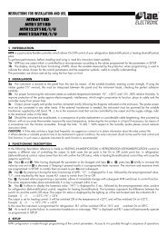
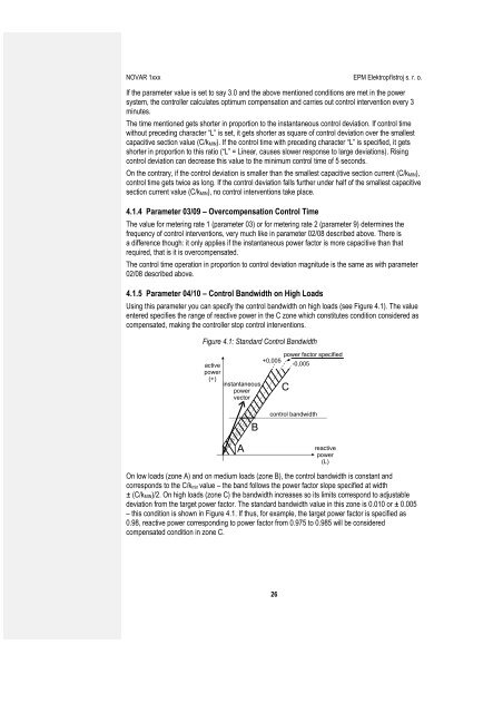
Using this parameter you can specify the control bandwidth on high loads (see Figure 4.1). The value<br />
entered specifies the range of reactive power in the C zone which constitutes condition considered as<br />
compensated, making the controller stop control interventions.<br />
Figure 4.1: Standard Control Bandwidth<br />
active<br />
power<br />
(+)<br />
instantaneous<br />
power<br />
vector<br />
power factor specified<br />
+0,005<br />
-0,005<br />
C<br />
B<br />
control bandwidth<br />
A<br />
reactive<br />
power<br />
(L)<br />
On low loads (zone A) and on medium loads (zone B), the control bandwidth is constant and<br />
corresponds to the C/k min value – the band follows the power factor slope specified at width<br />
± (C/k MIN)/2. On high loads (zone C) the bandwidth increases so its limits correspond to adjustable<br />
deviation from the target power factor. The standard bandwidth value in this zone is 0.010 or ± 0.005<br />
– this condition is shown in Figure 4.1. If thus, for example, the target power factor is specified as<br />
0.98, reactive power corresponding to power factor from 0.975 to 0.985 will be considered<br />
compensated condition in zone C.<br />
26