NOVAR 1106 / 1114 / 1206 / 1214 NOVAR 1xxx / S400 NOVAR ...
NOVAR 1106 / 1114 / 1206 / 1214 NOVAR 1xxx / S400 NOVAR ...
NOVAR 1106 / 1114 / 1206 / 1214 NOVAR 1xxx / S400 NOVAR ...

Create successful ePaper yourself
Turn your PDF publications into a flip-book with our unique Google optimized e-Paper software.
Elektropřístroj s.r.o.<br />
Mezi Vodami 1955, 143 00 Praha 4 - Modřany<br />
Czech Republic<br />
tel. +420 261 106 111, fax +420 261 106 106<br />
email : epm@epm.cz<br />
internet : www.epm.cz; www.kmbsystems.eu<br />
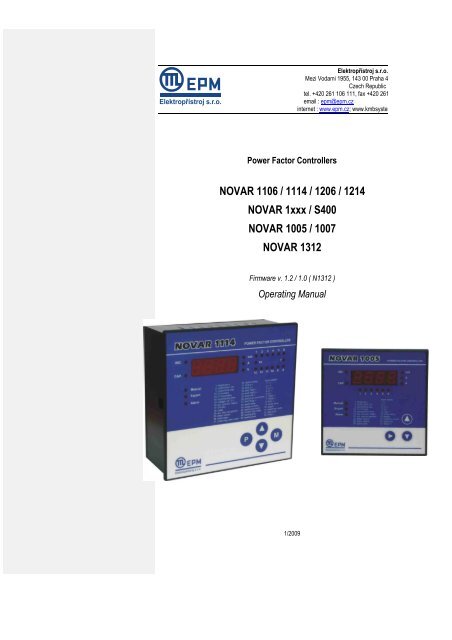
Power Factor Controllers<br />
<strong>NOVAR</strong> <strong>1106</strong> / <strong>1114</strong> / <strong>1206</strong> / <strong>1214</strong><br />
<strong>NOVAR</strong> <strong>1xxx</strong> / <strong>S400</strong><br />
<strong>NOVAR</strong> 1005 / 1007<br />
<strong>NOVAR</strong> 1312<br />
Firmware v. 1.2 / 1.0 ( N1312 )<br />
Operating Manual<br />
1/2009
<strong>NOVAR</strong> <strong>1xxx</strong> EPM Elektropřístroj s. r. o.<br />
LIST OF CONTENTS<br />
1. DESCRIPTION .................................................................. 5<br />
1.1 Manual Structure .................................................................................................................................. 5<br />
1.2 <strong>NOVAR</strong> <strong>1106</strong>/<strong>1114</strong>/<strong>1206</strong>/<strong>1214</strong> Essential Functions ........................................................................... 5<br />
1.3 <strong>NOVAR</strong> Controller Version “/<strong>S400</strong>” .................................................................................................... 6<br />
1.4 <strong>NOVAR</strong> 1005 / 1007............................................................................................................................... 6<br />
1.5 <strong>NOVAR</strong> 1312.......................................................................................................................................... 6<br />
1.6 History of Firmware Versions.............................................................................................................. 6<br />
1.7 Front Panel ............................................................................................................................................ 7<br />
1.8 Numeric Display ................................................................................................................................... 7<br />
1.8.1 <strong>NOVAR</strong> 11xx / 12xx / 13xx Controllers .......................................................................................... 7<br />
1.8.1.1 Instantaneous Measurement Values ......................................................................................... 7<br />
1.8.1.2 Main Branch .............................................................................................................................. 7<br />
1.8.1.2.1 COS Branch ........................................................................................................................ 9<br />
1.8.1.2.2 A Branch ........................................................................................................................... 10<br />
1.8.1.2.3 V Branch ........................................................................................................................... 11<br />
1.8.1.3 Controller Parameters ............................................................................................................. 12<br />
1.8.2 <strong>NOVAR</strong> 10xx Controllers ............................................................................................................. 13<br />
1.8.3 Test and Error Messages ............................................................................................................ 13<br />
1.9 Indication LEDs .................................................................................................................................. 13<br />
1.9.1 Output State Indications .............................................................................................................. 14<br />
1.9.2 Trend Indication ........................................................................................................................... 14<br />
1.9.3 Indication of Manual Mode .......................................................................................................... 14<br />
1.9.4 Indication of Backfeed (Power Export) ........................................................................................ 14<br />
1.9.5 Alarm Indication ........................................................................................................................... 14<br />
2. INSTALLATION .............................................................. 15<br />
2.1 Physical ............................................................................................................................................... 15<br />
2.2 Connection .......................................................................................................................................... 15<br />
2.2.1 Power Supply............................................................................................................................... 15<br />
2.2.1.1 Standard Version Controllers .................................................................................................. 15<br />
2.2.1.2 ―/<strong>S400</strong>‖ Version Controllers ..................................................................................................... 16<br />
2.2.1.3 <strong>NOVAR</strong> 1005 / 1007 Controllers ............................................................................................. 16<br />
2
<strong>NOVAR</strong> <strong>1xxx</strong> EPM Elektropřístroj s. r. o.<br />
2.2.1.4 Protection ................................................................................................................................ 17<br />
2.2.2 Measurement Voltage ................................................................................................................. 17<br />
2.2.2.1 11xx and 10xx Line Controllers ............................................................................................... 17<br />
2.2.2.2 12xx Line Controllers .............................................................................................................. 17<br />
2.2.3 Measurement Current.................................................................................................................. 17<br />
2.2.4 Error Indication ............................................................................................................................ 18<br />
2.2.4.1 <strong>NOVAR</strong> 11xx / 12xx / 13xx Controllers ................................................................................... 18<br />
2.2.4.2 <strong>NOVAR</strong> 10xx Controllers......................................................................................................... 18<br />
2.2.5 Output Relays .............................................................................................................................. 18<br />
2.2.5.1 Standard Version Controllers .................................................................................................. 18<br />
2.2.5.2 ―/<strong>S400</strong>‖ Version Controllers ..................................................................................................... 18<br />
2.2.6 Second Metering Rate, External Alarm ....................................................................................... 18<br />
2.2.7 Communication Interface ............................................................................................................. 19<br />
2.2.7.1 RS-232 Communication Interface ........................................................................................... 19<br />
2.2.7.2 RS-485 Communication Interface ........................................................................................... 19<br />
3. PUTTING IN OPERATION ............................................. 20<br />
3.1 First Use .............................................................................................................................................. 20<br />
3.2 Automatic connection configuration detection process................................................................ 20<br />
3.3 Automatic Section Power Recognition Process ............................................................................. 21<br />
4. OPERATION ................................................................... 24<br />
4.1 Setup ................................................................................................................................................... 24<br />
4.1.1 Editing Parameters and Clearing Recorded Measurement Values ............................................. 24<br />
4.1.1.1 Parameter Editing ................................................................................................................... 24<br />
4.1.1.2 Clearing Recorded Measurement Values ............................................................................... 24<br />
4.1.1.3 Enable / Disable Parameter Edit ............................................................................................. 24<br />
4.1.2 Parameter 01/07 – Target Power Factor ..................................................................................... 25<br />
4.1.3 Parameter 02/08 – Undercompensation Control Time ................................................................ 25<br />
4.1.4 Parameter 03/09 – Overcompensation Control Time .................................................................. 26<br />
4.1.5 Parameter 04/10 – Control Bandwidth on High Loads ................................................................ 26<br />
4.1.6 Parameter 06 – Metering Rate 2 Operation ................................................................................ 28<br />
4.1.7 Parameters 12,13 – Metering Current Transformer (CT) Ratio ................................................... 29<br />
4.1.8 Parameter 14 – Reconnection Delay Time .................................................................................. 29<br />
4.1.9 Parameters 15, 16 – Type of Measurement Voltage and Connection Configuration .................. 29<br />
4.1.9.1 Setting Type of Connection Configuration if Measuring at Power Supply Transformer’s<br />
Opposite Sides ......................................................................................................................................... 30<br />
4.1.10 Parameter 17 – Metering Voltage Transformer (VT) Turns Ratio ............................................... 31<br />
4.1.11 Parameter 18 – Compensation System Nominal Voltage (UNOM) ............................................... 32<br />
4.1.12 Parameter 20 – Automatic Section Power Recognition Process ................................................. 32<br />
4.1.13 Parameter 21, 22 – Switching Program, Selection of Linear Switching Mode and Smallest<br />
Capacitor (C/ kMIN) Nominal Power ............................................................................................................... 32<br />
4.1.14 Number of Capacitors .................................................................................................................. 34<br />
4.1.15 Parameter 25 – Compensation Section Nominal Power ............................................................. 34<br />
4.1.16 Parameter 26 – Fixed Sections, Switching Cooling and Heating, Alarm ..................................... 35<br />
4.1.16.1 Fixed Sections .................................................................................................................... 35<br />
4.1.16.2 Switching Cooling and Heating ........................................................................................... 35<br />
4.1.16.3 Alarm Signalling ( <strong>NOVAR</strong> 10xx only ) ................................................................................ 35<br />
4.1.17 Parameter 27 – Limit Power Factor for Compensation by Choke ............................................... 36<br />
4.1.18 Parameter 30 – Alarm Setting ..................................................................................................... 36<br />
4.1.18.1 Alarm Indication .................................................................................................................. 36<br />
4.1.18.2 Alarm Actuation .................................................................................................................. 38<br />
4.1.19 Parameters 31 through 37 – Alarm Indication/Actuation Limits ................................................... 38<br />
4.1.20 Parameter 40 – Alarm Status ...................................................................................................... 39<br />
3
<strong>NOVAR</strong> <strong>1xxx</strong> EPM Elektropřístroj s. r. o.<br />
4.1.21 Parameters 43, 44 – Total Section Connection Time and Number of Section Switching<br />
Operations ..................................................................................................................................................... 39<br />
4.1.22 Parameter 45 – Type of Controller Error ..................................................................................... 39<br />
4.1.23 Parameter 46 – Control Time ...................................................................................................... 40<br />
4.1.24 Parameters 50, 51, 52 – Instrument Address, Communication Rate and Communication Protocol40<br />
4.1.25 Parameter 55 – Power System Frequency .................................................................................. 40<br />
4.1.26 Parameters 56, 57 – average, maximum, minimum value evaluation window size ..................... 41<br />
4.1.27 Parameter 58 – Temperature Display °C / °F ............................................................................. 41<br />
4.1.28 Parameters 59, 60 – Cooling and Heating Switching Thresholds ............................................... 41<br />
4.2 Section Value Accurization ............................................................................................................... 41<br />
4.3 Faulty Section Indication and Disablement ..................................................................................... 42<br />
4.4 Compensation by Choke ................................................................................................................... 43<br />
4.5 Control Interruption ........................................................................................................................... 44<br />
4.6 Manual Mode ....................................................................................................................................... 44<br />
4.7 Manual Intervention in Control Process .......................................................................................... 44<br />
4.8 Controller Initialization ...................................................................................................................... 45<br />
4.9 Capacitor Harmonic Load factor (CHL) ............................................................................................ 45<br />
4.10 Text Messages .................................................................................................................................... 48<br />
5. <strong>NOVAR</strong>1312 DESCRIPTION .......................................... 49<br />
5.1 Basic Operation .................................................................................................................................. 49<br />
5.2 History of Firmware Versions............................................................................................................ 49<br />
5.3 Installation .......................................................................................................................................... 49<br />
5.3.1 Transistor Outputs ....................................................................................................................... 49<br />
5.3.2 Relay Outputs .............................................................................................................................. 50<br />
5.4 Operation ............................................................................................................................................ 50<br />
5.4.1 Thyristor and Contactor Group .................................................................................................... 50<br />
5.4.2 Control Principles......................................................................................................................... 50<br />
5.5 Setup ................................................................................................................................................... 51<br />
5.5.1 Parameter 28 – Number of Capacitors in Thyristor Group .......................................................... 51<br />
5.5.2 Parameter 29 – Thyristor Group Control Rate and Reconnection Delay Time ............................ 51<br />
5.5.2.1 Control Operation at the Highest Control Rate ........................................................................ 52<br />
6. WIRING EXAMPLES ...................................................... 55<br />
7. TECHNICAL SPECIFICATIONS .................................... 64<br />
8. MAINTENANCE, TROUBLESHOOTING ....................... 66<br />
4
<strong>NOVAR</strong> <strong>1xxx</strong> EPM Elektropřístroj s. r. o.<br />
1. Description<br />
1.1 Structure of this Manual<br />
The manual has two principal parts. The first one describes <strong>NOVAR</strong> <strong>1106</strong>, <strong>NOVAR</strong> <strong>1114</strong>, <strong>NOVAR</strong><br />
<strong>1206</strong> and <strong>NOVAR</strong> <strong>1214</strong> power factor controllers including ―/<strong>S400</strong>‖ version, and simple <strong>NOVAR</strong> 1005<br />
and <strong>NOVAR</strong> 1007 models.<br />
<strong>NOVAR</strong> 1312 power factor controller, designed for rapid power factor compensation, uses the<br />
concepts of <strong>NOVAR</strong><strong>1214</strong>; most of their features and operations are identical. That is why description<br />
of <strong>NOVAR</strong>1312 is in a separate chapter at the end of this manual, and it covers specific featuresof<br />
that controller only.<br />
1.2 <strong>NOVAR</strong> <strong>1106</strong>/<strong>1114</strong>/<strong>1206</strong>/<strong>1214</strong> - Essential Functions<br />
<strong>NOVAR</strong> <strong>1xxx</strong> reactive power controllers are fully automatic instruments that allow optimum control of<br />
reactive power compensation. They take their design concepts from the series <strong>NOVAR</strong> 1xx/2xx,<br />
bringing up a number of improvements and new features while keeping the way of operation.<br />
The instruments feature precise voltage and current measurement circuits, while the digital processing<br />
of values measured provides high evaluation accuracy of both true root–mean–square values of<br />
voltage, current and power factor values. The built-in temperature sensor measures the temperature<br />
inside the distribution board cubicle.<br />
The instruments calculate fundamental harmonic component of active and reactive current with FFT<br />
algorithm. Voltage fundamental harmonic component is calculated in an analogous manner thus<br />
providing accurate measurement and control even in conditions of distortion by higher harmonic<br />
components.<br />
The voltage measurement circuit of the <strong>NOVAR</strong> <strong>1106</strong>/<strong>1114</strong> is internally connected to the power supply<br />
terminals; it is insulated in <strong>NOVAR</strong><strong>1206</strong>/<strong>1214</strong>, allowing connection of any voltage within the range<br />
from 45 to 760 V AC. The power system frequency can vary within the range from 43 to 67 Hz. The<br />
current measurement input is a general–purpose one for nominal value of 1 A or 5 A metering current<br />
transformer’s secondary side. The measurement inputs can be connected to the controller in any<br />
combination, that is any phase or line voltage and any phase’s current.<br />
The instrument’s installation is fully automatic. The controller automatically detects both the<br />
connection configuration and the value of each compensation section connected. Entering these<br />
parameters manually is also possible.<br />
Control is provided in all four quadrants and its speed depends on both control deviation value and its<br />
polarization (overcompensation / undercompensation). Connecting and disconnecting power factor<br />
capacitors is carried out in such a way that achieving the optimum compensation condition is by a<br />
single control intervention at minimum number of sections connected. At the same time, the<br />
instrument chooses relay sections with regard to their even load and preferably connects those that<br />
have been disconnected for the longest time and the remanent charge of which is thus minimum.<br />
Within the control process the instrument continually checks the relay compensation sections. If<br />
a section’s outage or change in value is detected, the section is temporarily disabled from control<br />
under relevant setting. The section temporarily disabled is periodically tested and enabled for control<br />
again when possible.<br />
In measurement, harmonic component levels of both voltage and current are evaluated up to the 19 th<br />
order. The current ’s Total Harmonic Distortion, THD, and the Capacitor Harmonic Load, CHL that can<br />
be viewed on a display, are calculated from these measurements’ results while it is possible to preset<br />
the THD and the CHL threshold levels at which the controller disconnects all compensation sections<br />
thus preventing their damage. Besides that, the most adverse values are recorded into the<br />
instrument’s memory for subsequent analysis.<br />
5
<strong>NOVAR</strong> <strong>1xxx</strong> EPM Elektropřístroj s. r. o.<br />
Besides the power factor capacitors, it is possible to connect power factor chokes (power system<br />
decompensation). Any output can be set as fixed, the two highest outputs can also be used to connect<br />
the cooling or heating circuits.<br />
The controllers come in two basic designs with different numbers of outputs: <strong>NOVAR</strong><strong>1106</strong>/<strong>1206</strong> with<br />
six output relays and <strong>NOVAR</strong><strong>1114</strong>/<strong>1214</strong> with fourteen output relays. The <strong>NOVAR</strong>12xx controllers<br />
have, as opposed to the 11xx line, an additional voltage measurement input and a second metering<br />
rate input.<br />
Both types of controller have an Alarm relay output that can be set to indicate non-standard<br />
conditions, such as undercurrent, overcurrent, measurement voltage failure, overvoltage, harmonic<br />
distortion preset threshold exceeded, overcompensation or undercompensation, section limit<br />
connection rate exceeded, section outage, backfeed condition (power export) or overheating.<br />
All types of the controller can be ordered in a version featuring an optional galvanic-insulated RS-232<br />
or RS-485 communication interface. All values measured can be then monitored and the controller’s<br />
parameters set using a remote computer.<br />
1.3 <strong>NOVAR</strong> Controller Version “/<strong>S400</strong>”<br />
Controllers of version ―/<strong>S400</strong>‖ ( model marking example : <strong>NOVAR</strong>-<strong>1114</strong>/<strong>S400</strong>) diifer from standard<br />
version of the <strong>NOVAR</strong>-<strong>1106</strong> / <strong>NOVAR</strong>-<strong>1114</strong> / <strong>NOVAR</strong>-<strong>1206</strong> / <strong>NOVAR</strong>-<strong>1214</strong> models in following<br />
aspects :<br />
<br />
<br />
increased maximum power supply voltage up to 500 V, both AC and DC<br />
relays’ common contacts insulated, connected to additional terminals<br />
The ―/<strong>S400</strong>‖-version instruments can be used at insulated networks (without neutral wire). The other<br />
features are identical to those of standard version.<br />
1.4 <strong>NOVAR</strong>1005 / 1007<br />
These models are simplified versions of the <strong>NOVAR</strong><strong>1106</strong> / <strong>1114</strong> models. They are built in smaller box<br />
and designed for less demanding applications. <strong>NOVAR</strong>1005 features 6 output relays, <strong>NOVAR</strong>1007<br />
features 8 output relays.<br />
1.41.5 <strong>NOVAR</strong>1312<br />
<strong>NOVAR</strong>1312 is designed to provide rapid compensation using thyristor switches. It differs from<br />
<strong>NOVAR</strong><strong>1214</strong> in the two following principal aspects:<br />
<br />
<br />
outputs 1 through 12 are transistor-driven<br />
control speed for these outputs can be set up to 25 interventions a second<br />
<strong>NOVAR</strong>1312 specific features are described in a separate chapter. The other features are identical to<br />
those of <strong>NOVAR</strong><strong>1214</strong>.<br />
1.51.6 History of Firmware Versions<br />
version date of release note<br />
1.0 3/2006 - basic version<br />
1.1 4/2007 - 2nd metering rate functionality bug fix<br />
- linear switching mode added to parameter 21<br />
1.2 9/2007 - external alarm (No. 14) function added<br />
6
<strong>NOVAR</strong> <strong>1xxx</strong> EPM Elektropřístroj s. r. o.<br />
1.61.7 Front Panel<br />
The front panel consists of a numeric display, indication LEDs and control keys.<br />
Figure 1.1: Front Panel<br />
1.71.8 Numeric Display<br />
Information shown on the numeric display can be divided into 3 main data groups:<br />
instantaneous power system values measured, such as power factor, current, voltage,<br />
power, etc.<br />
controller parameters<br />
test and error messages<br />
1.7.11.8.1 <strong>NOVAR</strong> 11xx / 12xx / 13xx Controllers<br />
1.7.1.11.8.1.1 Instantaneous Measurement Values<br />
The mode of displaying instantaneous values is the basic display mode which the controller enters on<br />
power-up. If you switch to parameter display mode, you can get back to instantaneous value display<br />
mode by pressing the M (Measurement) button.<br />
The controller enters the instantaneous display mode automatically in about 30 seconds from the<br />
moment you stop pressing control keys (or in five minutes if control time is displayed – see description<br />
of parameter 46 further below).<br />
1.7.1.21.8.1.2 Main Branch<br />
One LED, COS or A or V, is always lit in the instantaneous display mode. These LEDs identify the<br />
value group displayed. Instantaneous values displayed are organized in branches – see Figure 1.2.<br />
The main branch contains the following main instantaneous values: cos, Ieff and Ueff. You can<br />
switch between the values displayed using the ▲, ▼ buttons.<br />
7
<strong>NOVAR</strong> <strong>1xxx</strong> EPM Elektropřístroj s. r. o.<br />
Figure 1.2: Instantaneous value display – structure<br />
main branch<br />
cos<br />
Ieff<br />
M<br />
Ueff<br />
F<br />
M<br />
voltage<br />
branch<br />
M<br />
Iact<br />
Irea<br />
current<br />
branch<br />
Pac<br />
Pre<br />
dPre<br />
cos branch<br />
CHL<br />
dIrea<br />
Temp<br />
THDU<br />
THDI<br />
Acos<br />
3 rd harU<br />
3 rd harI<br />
mincos<br />
s<br />
…<br />
5 th harI<br />
APac<br />
19 th harU<br />
…<br />
maxPac<br />
maxCHL<br />
17 th harI<br />
APre<br />
maxTHDU<br />
maxhar3U<br />
…<br />
19 th harI<br />
19<br />
maxTHDI<br />
h<br />
a<br />
r<br />
maxPre<br />
maxdPre<br />
maxTemp<br />
h<br />
a<br />
r h<br />
a<br />
r<br />
mxhar19U<br />
Table 1.1: List of Measurement Quantities – Main Branch<br />
abbreviation symbol quantity unit<br />
cos - Instantaneous power factor. The value corresponds to the ratio of -<br />
instantaneous active component to instantaneous total power<br />
fundamental harmonic value in the power system. A positive value<br />
means inductive power factor, negative means capacitive power<br />
factor.<br />
Ieff - Instantaneous current effective value in the power systems A / kA *<br />
(including higher harmonic components).<br />
Ueff - Instantaneous voltage effective value in the power system<br />
V (kV)<br />
(including higher harmonic components). By default shown in<br />
volts. If the measurement voltage is connected via a metering<br />
transformer, in kilovolts (see description of parameter 17).<br />
* … in A as default; flashing decimal point indicates value in kA<br />
8<br />
M
<strong>NOVAR</strong> <strong>1xxx</strong> EPM Elektropřístroj s. r. o.<br />
Pressing the M button switches to the relevant subbranch: to the branch of power factors, power, and<br />
temperature while displaying COS (further as COS Branch), to the current branch while displaying Ieff<br />
(further as A Branch) or to the voltage branch while displaying Ueff (further as V Branch). Again, you<br />
can move up and down the branch using the ▲, ▼ buttons. Displaying values of the subbranches’<br />
quantities is indicated with periodic flashes of the quantity symbol. To get back to the main branch of<br />
instantaneous values press button M.<br />
Tables 1.1 through 1.4 show descriptions of the measurement quantities.<br />
1.7.1.2.11.8.1.2.1 COS Branch<br />
Instantaneous power values as well as recorded average, maximum and minimum values of selected<br />
quantities are shown in the COS Branch. Power is displayed as three-phase values (single-phase<br />
power values multiplied by three). Reactive power values are prefixed with L for positive values and C<br />
for negative values.<br />
The values recorded can be divided by their nature into three groups:<br />
1. Average values Acos, APac, APre<br />
These are average values of power factor, active and reactive power. The depth of average<br />
can be set in parameter 56 from 1 minute to 7 days.<br />
Note: The average values of active and reactive power are rendered with the sign. If then, for<br />
example, the reactive power value is changing its polarity (it has alternately inductive and<br />
capacitive character), its average value, APre, may become zero even though the<br />
instantaneous reactive power value was not zero at any point in time under evaluation. Also<br />
the power factor average value, which is evaluated from the average active and reactive<br />
power using the formula<br />
Acos =<br />
APac<br />
2<br />
APac APre<br />
may, in such an event, become 1 even though the instantaneous power factor was never 1<br />
within the time evaluated.<br />
2. Maximum and minimum values mincos, maxPac, maxPre, maxdPre<br />
<br />
<br />
<br />
mincos – evaluated as a ratio of fundamental harmonic active and reactive power<br />
moving averages. The moving average window size can be specified in parameter<br />
57 from 1 minute to 7 days. The minimum value is recorded and displayed.<br />
Evaluation is conditioned by the corresponding average current being at least 5% of<br />
the nominal load as determined from the metering current transformer turns ratio<br />
primary value (parameter12) else the value is ignored (the value is not recorder for<br />
minimum loads).<br />
maxPac, maxPre – the maximum values of fundamental harmonic active and<br />
reactive power moving averages. The moving average window size can be specified<br />
in parameter 57 from 1 minute to 7 days.<br />
maxdPre – the maximum value of fundamental harmonic absent reactive power<br />
moving average. As opposed to the absent reactive power instantaneous value,<br />
dPre, which is the difference between the actual and required reactive power,<br />
irrespective of the instantaneous condition of the controller’s closed outputs,<br />
maxdPre is only evaluated if the required reactive power exceeds the system’s<br />
control capacity (that is the total power of all compensation banks, or sections), and<br />
its value is determined as a difference between this control capacity and required<br />
power (if the control capacity is sufficient, the maxdPre value is zero). The moving<br />
average window size can be specified in parameter 57 from 1 minute to 7 days.<br />
3. Maximum temperature maxTemp<br />
9<br />
2
<strong>NOVAR</strong> <strong>1xxx</strong> EPM Elektropřístroj s. r. o.<br />
The temperature moving average maximum value. The moving window depth is fixed at<br />
1 minute.<br />
The above described recorded values can be cleared, each group separately – when clearing a value,<br />
all other values in the same groups are cleared too. Clearing values is explained in the Editing chapter<br />
further down the manual.<br />
Table 1.2: List of Measurement Quantities – COS Branch<br />
abbreviation symbol quantity unit<br />
Pac Instantaneous fundamental harmonic active power (Power kW / MW *<br />
active).<br />
Pre Instantaneous fundamental harmonic reactive power (Power kvar / Mvar *<br />
reactive).<br />
dPre Instantaneous fundamental harmonic reactive power<br />
kvar / Mvar *<br />
difference to achieve target power factor (Delta Power<br />
reactive).<br />
Temp or Instantaneous temperature (in the distribution board cabinet, °C or °F<br />
at the controller). Displayed in degrees Celsius or Fahrenheit,<br />
<br />
as specified in parameter 58.<br />
Acos Average power factor in the power system over the time<br />
—<br />
specified in parameter 56 (Average cos).<br />
mincos Minimum power factor in the power system achieved since<br />
—<br />
last clear. The evaluation window is specified in parameter 57.<br />
APac Average fundamental harmonic active power in the power kW / MW *<br />
system over the time specified in parameter 56 (Average<br />
<br />
Power active).<br />
maxPac Maximum fundamental harmonic active power in the power kW / MW *<br />
system achieved since last clear. The evaluation window is<br />
specified in parameter 57 (Maximum Power active).<br />
APre<br />
maxPre<br />
maxdPre<br />
maxTemp<br />
<br />
Average fundamental harmonic reactive power in the power<br />
system over the time specified in parameter 56 (Average<br />
Power active).<br />
Maximum fundamental harmonic reactive power in the power<br />
system achieved since last clear. The evaluation window is<br />
specified in parameter 57 (Maximum Power reactive).<br />
Maximum fundamental harmonic reactive power difference to<br />
achieve target power factor in the power system achieved<br />
since last clear. The evaluation window is specified in<br />
parameter 57 (Maximum Delta Power reactive).<br />
or<br />
<br />
Maximum temperature recorded since last clear. The<br />
evaluation is based on temperature one-minute moving<br />
averages (Maximum Temperature).<br />
* … in kW-, kvar- units as default; flashing decimal point indicates value in MW, Mvar<br />
1.7.1.2.21.8.1.2.2 A Branch<br />
All quantities related to current are shown in this branch. The maxTHDI value can be cleared<br />
manually.<br />
kvar / Mvar *<br />
kvar / Mvar *<br />
kvar / Mvar *<br />
°C or °F<br />
Table 1.3: List of Measurement Quantities – A Branch<br />
10
<strong>NOVAR</strong> <strong>1xxx</strong> EPM Elektropřístroj s. r. o.<br />
abbreviation symbol quantity unit<br />
Iact Instantaneous active current fundamental harmonic component A / kA *<br />
(active).<br />
Irea Instantaneous reactive current fundamental harmonic component A / kA *<br />
(reactive); L indicates inductive, C indicates capacitive polarity.<br />
dIrea Instantaneous reactive current fundamental harmonic component A / kA *<br />
difference to achieve the target power factor in the power system<br />
(Delta reactive).<br />
THDI Instantaneous level of power system current’s total harmonic<br />
%<br />
distortion (Total Harmonic Distortion) – shows the ratio of current<br />
higher harmonic components content, up to the 19 th harmonic, to the<br />
level of fundamental harmonic. It is only evaluated if the total power<br />
system load is at least 5% of the nominal load in terms of current<br />
determined by the metering current transformer conversion primary<br />
side value (parameter 12).<br />
3. ÷ 19.har Instantaneous current harmonic component level in the power<br />
%<br />
÷ system.<br />
maxTHDI Maximum THDI value achieved since last clear. The evaluation is %<br />
based on THDI one-minute moving averages.<br />
* … in A as default; flashing decimal point indicates value in kA<br />
1.7.1.2.31.8.1.2.3 V Branch<br />
This branch shows all the quantities related to voltage. They are commonly used quantities. Only the<br />
Capacitor Harmonic Load, CHL, factor needs further explanation – details to be found in chapter 4.9<br />
further below.<br />
The maximum values can be cleared manually. Clearing any of these values clears all the other<br />
maximum values within this branch.<br />
Table 1.4: List of Measurement Quantities – V Branch<br />
abbreviation symbol quantity unit<br />
F Instantaneous voltage fundamental harmonic component<br />
Hz<br />
frequency.<br />
CHL Instantaneous value of Capacitor Harmonic Load factor (Capacitor %<br />
Harmonic Load).<br />
%<br />
THDU Instantaneous level of power system voltage’s total harmonic<br />
distortion (Total Harmonic Distortion) – shows the ratio of current<br />
higher harmonic components content, up to the 19 th harmonic, to<br />
3. ÷<br />
19.har<br />
maxCHL<br />
maxTHDU<br />
3. ÷ 19.<br />
maxharI<br />
<br />
÷<br />
<br />
<br />
the level of fundamental harmonic.<br />
Instantaneous level of harmonic component voltage in the power<br />
system.<br />
Maximum CHL value achieved since last clear. The evaluation is<br />
based on CHL one-minute moving averages.<br />
Maximum THDU value achieved since last clear. The evaluation is<br />
based on THDU one-minute moving averages.<br />
Maximum value of voltage harmonic component achieved since<br />
÷ last clear. The evaluation is based on harmonic component oneminute<br />
moving averages.<br />
%<br />
%<br />
%<br />
%<br />
11
<strong>NOVAR</strong> <strong>1xxx</strong> EPM Elektropřístroj s. r. o.<br />
1.7.1.31.8.1.3 Controller Parameters<br />
You can view controller parameters by pressing the P button (parameters). First the parameter<br />
number shows momentarily and then its value does. The parameter number flashes momentarily<br />
every five seconds for better orientation.<br />
The parameters can be divided into three main groups:<br />
Parameters determining controller functions. These parameters can be set to direct the<br />
control process. There are target power factor, control period, reconnection delay time,<br />
etc.<br />
Parameters indicating controller’s current condition. This is the alarm (parameter 40),<br />
error condition (parameter 45), and control time (parameter 46). These parameters’<br />
values are set by the controller and they identify nonstandard or error conditions and<br />
monitor progress of the control process in detail.<br />
Total connected times recorded and numbers of connections of each compensation<br />
banks, or sections (parameters 43 and 44, respectively). These values are set by the<br />
controller and the operator can only clear them.<br />
The parameters are organized by ordinal number in the main branch – see Figure 1.3. Some of the<br />
parameters (parameter 25 – sectional power, 26 – fixed sections, 30 – alarm setting, 40 – state of<br />
alarm, 43 – total connected times, 44 – number of sections connected) are located on side branches<br />
for easier navigation. You can switch to a side branch with selected parameters by pressing button P<br />
(parameters) and switch back to the main branch in the same way. Side branch parameter displayed<br />
are identified by a dash between the parameter number and value. For example: in the main branch,<br />
while showing parameter 26 (fixed sections), you will see 01 C (section 1 is a capacitive<br />
compensation one); if you want to display conditions of the other sections, you need to switch display<br />
to the side branch by pressing button P; the display will change to 01–C and now you can move up<br />
and down the branch, through all sections’ values. Pressing button P again returns display to the main<br />
branch (the dash disappears).<br />
Figure 1.3: Parameter Display – Structure<br />
P-01<br />
P-02<br />
side branch<br />
P-03<br />
01-C<br />
P<br />
P-25<br />
main branch<br />
14-C<br />
P-xx<br />
Pressing button M (measurement) returns to the instantaneous value display mode. The controller<br />
gets back to this mode automatically in about 30 seconds from the last press of button.<br />
12
<strong>NOVAR</strong> <strong>1xxx</strong> EPM Elektropřístroj s. r. o.<br />
Exception: In the Manual mode the parameter values cannot be viewed. Instantaneous output values<br />
are displayed on pressing button P (parameters) — see description further below.<br />
Formatted: Bullets and Numbering<br />
1.6.11.8.2 <strong>NOVAR</strong> 10xx Controllers<br />
<strong>NOVAR</strong> 1005 and <strong>NOVAR</strong> 1007 controllers are equipped with 3 buttons only – instead M- and P-<br />
buttons, they features one ►- button.<br />
Listing through windows is analogic; the only difference is that both instantaneous measured values<br />
and controller parameters are situated in one common main branch, one below another ( see Fig.1.4 ).<br />
Fig. 1.4 : Instantaneous values and parameters (<strong>NOVAR</strong> 1005 / 1007)<br />
main branch<br />
cos<br />
Ieff<br />
►<br />
Ueff<br />
P-01<br />
F<br />
►<br />
voltage<br />
branch<br />
►<br />
Iact<br />
Irea<br />
current<br />
branch<br />
…<br />
cos branch<br />
Pac<br />
Pre<br />
…<br />
P-02<br />
CHL<br />
…<br />
…<br />
P-03<br />
…<br />
…<br />
…<br />
P-25<br />
P-26<br />
…<br />
►<br />
side branch<br />
01-C<br />
02-C<br />
…<br />
P-xx<br />
08-C<br />
1.7.31.8.3 Test and Error Messages<br />
In the instantaneous value display mode a test or error message pops up in place of an instantaneous<br />
power factor value in some situations. Each message is described further below in more detail. In<br />
these situations, if the value shown does not represent instantaneous power factor, the COS LED<br />
flashes.<br />
1.81.9 Indication LEDs<br />
Besides the numeric display and adjacent LEDs, COS , A , V, the front panel has some more<br />
indication LEDs.<br />
13
<strong>NOVAR</strong> <strong>1xxx</strong> EPM Elektropřístroj s. r. o.<br />
1.8.11.9.1 Output State Indications<br />
The array of LEDs at the top right of the front panel show the current state of output relays. Each LED<br />
is assigned a number from 1 to 14, and if lit, they indicate closed contacts of the corresponding output<br />
relay.<br />
If a LED is flashing, it means the controller wants to connect the output, but it has to wait for the delay<br />
time to elapse. The corresponding output relay contacts are open and they will be closed as soon as<br />
the reconnection delay time has elapsed.<br />
An exception is the power-up display test to check correct operation of all display elements. In this test<br />
the display shows TEST and all indication LEDs come on and go out one by one. All output relays stay<br />
open while the test is running.<br />
1.8.21.9.2 Trend Indication<br />
These LEDs show the magnitude of deviation of the true instantaneous reactive power in the power<br />
system from optimum reactive power value which would correspond to the specified value of required<br />
power factor.<br />
If the deviation is smaller than a half of the reactive power value of the smallest capacitor, both LEDs<br />
are dark. If the deviation is greater than a half of, but smaller than, the reactive power value of the<br />
smallest capacitor, the corresponding LED flashes — if lagging (undercompensation), the IND LED<br />
flashes; if leading (overcompensation), the CAP LED flashes. If the deviation exceeds the value of the<br />
smallest capacitor, the corresponding LED is permanently lit.<br />
Exceptions to these LEDs’ meanings are the following situations:<br />
measurement U and I method of connection is not defined (parameter 16)<br />
automatic connection configuration detection process is in progress<br />
automatic section power recognition process is in progress<br />
If the method of connection is not defined, both LEDs flash; they are dark in the other two situations.<br />
1.8.31.9.3 Indication of Manual Mode<br />
Flashing Manual LED indicates that the controller is in the manual mode. The controller’s automatic<br />
control function is disabled.<br />
If this LED is dark and display is in the Measurement mode, the controller is in its standard control<br />
mode or it is carrying out automatic connection configuration detection process or automatic section<br />
power recognition process.<br />
1.8.41.9.4 Indication of Backfeed (Power Export)<br />
If the controller knows of the method of connection (measurement voltage and current), that is if the<br />
automatic connection configuration detection process has been completed successfully or the method<br />
of connection has been entered manually, the Export LED indicates the power transmission direction.<br />
If it is dark, the power is flowing from the assumed power supply to the appliance. If the LED is lit, the<br />
power is flowing in the opposite direction.<br />
1.8.51.9.5 Alarm Indication<br />
An Alarm relay can be used for non-standard events signalling. This relay’s operation can be set up<br />
as described further below ( parameter 30 ). At <strong>NOVAR</strong> 10xx controllers that haven’t dedicated alarm<br />
relay it is necessary to select and set alarm relay function first ( parameter 26 ).<br />
The Alarm LED indicates this relay’s condition, that is if the Alarm relay’s output contact is closed, the<br />
LED flashes.<br />
14
<strong>NOVAR</strong> <strong>1xxx</strong> EPM Elektropřístroj s. r. o.<br />
2. Installation<br />
2.1 Physical<br />
The instrument is built in a plastic box to be installed in a distribution board panel. The instrument’s<br />
position must be fixed with locks.<br />
Natural air circulation should be provided inside the distribution board cabinet, and in the instrument’s<br />
neighbourhood, especially underneath the instrument, no other instrumentation that is source of heat<br />
should be installed or the temperature value measured may be false.<br />
2.2 Connection<br />
To connect the controller there are connectors with screw-on terminals in the back wall. Signal pinout<br />
on these connectors is illustrated in Figures 2.1 and 2.2.<br />
Examples of controller wiring are shown in a separate chapter.<br />
Fig. 2.1 : <strong>NOVAR</strong><strong>1114</strong> controller – connectors<br />
<strong>NOVAR</strong> <strong>1106</strong> <strong>1114</strong> / 232 485<br />
Serial / vers.:<br />
Product. date :<br />
U 100 ÷ 275 VAC, 7VA, 43 ÷ 67 Hz<br />
IP 4X<br />
Made in Czech Republic<br />
/<br />
/<br />
1 2 3 4 5 6 7 8 9 10 11 12 13 14<br />
ALARM<br />
k l L N<br />
Rx Tx GND<br />
RS 232/485<br />
max. 100÷275 VAC<br />
TR A B GND<br />
5A<br />
10A<br />
(1A)<br />
SUPPLY<br />
LOAD<br />
L1<br />
L2<br />
L3<br />
N<br />
Maximum cross section area of connection wires is 2.5 square millimetres.<br />
2.2.1 Power Supply<br />
2.2.1.1 Standard Version Controllers<br />
The controller requires supply voltage in the range as declared in technical specifications table for its<br />
operation.<br />
The supply voltage connects to terminals 3 (L) and 4 (N). In case of DC supply voltage the polarity of<br />
connection is free. Power supply voltage needs to be externally protected ( see chapter Protection<br />
below ).<br />
The 12xx line controllers have power supply terminals 3 (L) and 4 (N) internally connected to terminals<br />
5 (L) and 6 (N) which can be used to connect the power supply voltage to measurement voltage input<br />
(terminals 7 – L and 9 – N/L).<br />
Power supply terminal 3 (L) is internally connected to the common pole of output relays. It is<br />
necessary to dimension the power supply protection in consideration of output contactors’ power as<br />
well.<br />
15
<strong>NOVAR</strong> <strong>1xxx</strong> EPM Elektropřístroj s. r. o.<br />
Fig. 2.2 : <strong>NOVAR</strong><strong>1214</strong> Controller – Connectors<br />
Serial / vers.:<br />
Product. date :<br />
U 100 ÷ 275 VAC, 7VA, 43 ÷ 67 Hz<br />
IP 4X<br />
Made in Czech Republic<br />
/<br />
/<br />
1 2 3 4 5 6 7 8 9 10 11 12 13 14<br />
ALARM<br />
k l L N<br />
Rx Tx GND<br />
L N L L/N<br />
RS 232/485<br />
max. 100÷275 VAC 58÷690 VAC 2. TARIF<br />
TR A B GND<br />
5A<br />
10A<br />
(1A)<br />
max. 6A<br />
max. 6A<br />
SUPPLY<br />
LOAD<br />
L1<br />
L2<br />
L3<br />
N<br />
2.2.1.2 “/<strong>S400</strong>” Version Controllers<br />
Controllers of the ―/<strong>S400</strong>‖ version can be supplied with higher voltage – up to 500 V, either AC or DC.<br />
The power demand is the same as those of standard version.<br />
The supply voltage connects to terminals 3 (L1) and 5 (L2/N). In case of DC supply voltage the<br />
polarity of connection is generally free, but for maximum electromagnetic compatibility grounded pole<br />
should be connected to the terminal 5 (L2/N); see connection examples below.<br />
Power supply voltage need to be externally protected ( see following chapter).<br />
Despite of standard version, power supply terminal 3 (L) is not internally connected to the common<br />
pole of output relays. Terminals 4 and 6 are not used.<br />
Fig. 2.3 : <strong>NOVAR</strong><strong>1114</strong>/<strong>S400</strong> Controller – Connectors<br />
<strong>NOVAR</strong> <strong>1106</strong> <strong>1114</strong> / <strong>S400</strong> / 232 485<br />
Serial No / Fw. vers.: /<br />
Production date :<br />
U 75 ÷ 500 V AC, 7 VA, 43 ÷ 67 Hz<br />
IP 4X<br />
Made in Czech Republic<br />
/<br />
1 2 3 4 5 6 7 8 9 10 11 12 13 14<br />
ALARM<br />
k l L1 L2/N<br />
Rx Tx GND<br />
max.<br />
RS 232/485<br />
500<br />
TR A B GND<br />
5A<br />
VAC<br />
(1A)<br />
1A<br />
SUPPLY<br />
LOAD<br />
L1<br />
L2<br />
L3<br />
N<br />
Formatted: Bullets and<br />
Numbering<br />
2.2.1.3 <strong>NOVAR</strong> 1005 / 1007 Controllers<br />
The supply voltage connects to terminals 4 (L1) and 3 (N). In case of DC supply voltage the polarity of<br />
connection is free. Power supply voltage need to be externally protected ( see chapter Protection<br />
below ).<br />
Power supply terminal 4 ( L1 ) is internally connected to the common pole of output relays. It is<br />
necessary to dimension the power supply protection in consideration of output contactors’ power as<br />
well.<br />
16
<strong>NOVAR</strong> <strong>1xxx</strong> EPM Elektropřístroj s. r. o.<br />
Fig. 2.4 : <strong>NOVAR</strong> 1007 Controller – Connector<br />
<strong>NOVAR</strong> 1005 1007<br />
U~ 80÷275VAC,43÷67Hz<br />
Příkon 5 VA<br />
(7) (8)<br />
(1007)<br />
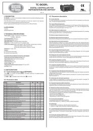
2.2.1.4 Protection<br />
Article 6.12.2.1 in the EN 61010-1 standard requires that instrument must have a disconnecting device<br />
in the power supply circuit (a switch — see installation diagram). It must be located at the instrument’s<br />
immediate proximity and easily accessible by the operator. The disconnecting device must be marked<br />
as such. A circuit breaker for nominal current of 10 amp makes a suitable disconnecting device, its<br />
function and working positions, however, must be clearly marked (symbols ―0‖ for power off and ―I‖ for<br />
power on in accordance with EN 61010–1).<br />
Since the controller’s inbuilt power supply is of pulse design, it draws momentary peak current on<br />
powerup which is in order of magnitude of amperes. This fact needs to be kept in mind when selecting<br />
the primary protection devices.<br />
2.2.2 Measurement Voltage<br />
2.2.2.1 11xx and 10xx Line Controllers<br />
The power supply voltage is used as measurement voltage in 11xx line controllers and it is not thus<br />
necessary (or possible) to connect measurement voltage independently.<br />
2.2.2.2 12xx Line Controllers<br />
The 12xx Line Controllers feature a general-purpose, galvanic-insulated voltage measurement input. It<br />
allows to connect measurement voltage in the range from 45 to 760 V AC at the frequency range 43<br />
to 67 Hz of either phase or line voltage. In basic connection phase L1 goes to terminal L (7) and<br />
neutral wire to terminal N/L (9).<br />
The measurement voltage must be protected externally. If the measurement voltage is identical with<br />
power supply voltage, they can share a circuit breaker. Otherwise each voltage branch must be<br />
protected with fuses or circuit breakers of nominal value 1 to 6 A.<br />
If the measurement voltage is connected via a metering voltage transformer, you have to enter the<br />
transformer turns ratio in instrument setup (parameter 17 – see further below) for correct expression of<br />
measurement values displayed.<br />
2.2.3 Measurement Current<br />
Metering current transformer (CT) outputs connect to terminals 1 (k) and 2 (l). At 10xx line controllers,<br />
connection polarity is opposite : terminal 1 is l and terminal 2 is k.<br />
A metering current transformer of nominal output current 5 or 1 A can be used – the metering current<br />
transformer’s ratio must be entered when setting up the instrument for proper measured values<br />
display (parameters 12, 13 – see further below). At <strong>NOVAR</strong>-11xx models, the connector features a<br />
screw lock to prevent accidental pull-out.<br />
17
<strong>NOVAR</strong> <strong>1xxx</strong> EPM Elektropřístroj s. r. o.<br />
2.2.4 Error Indication<br />
2.2.4.1 <strong>NOVAR</strong> 11xx / 12xx / 13xx Controllers<br />
The instrument has an auxiliary Alarm relay to indicate nonstandard conditions. This relay’s contact<br />
goes to terminals 17 and 18.<br />
2.2.4.2 <strong>NOVAR</strong> 10xx Controllers<br />
Non-standard events can be signalled by one of last two output relays (if they are not used for control).<br />
It is necessary to set such relay function properly, see parameter 26.<br />
2.2.5 Output Relays<br />
The instrument has 6, 8 or 14 output relays (depending on controller model). The relays’ contacts go<br />
to terminals 19 through 32 ( or 5 through 12 at <strong>NOVAR</strong>-10xx models).<br />
The relays’ output contacts are internally wired with varistors.<br />
2.2.5.1 Standard Version Controllers<br />
The relays’ common contacts are internally connected to power supply terminal L ( No. 3; or No. 4 at<br />
at <strong>NOVAR</strong>-10xx models). When an output relay contact closes, power supply voltage appears at the<br />
corresponding output terminal.<br />
2.2.5.2 “/<strong>S400</strong>” Version Controllers<br />
Despite of standard version, the relays’ common contacts are connected to additional terminals 33,<br />
34.<br />
In case of DC voltage for supplying of contactors, installation of suppression 2A/600V diodes directly<br />
at contactors´s coils is strongly recommended. Furthermore, note lower maximum current load of the<br />
controller outputs at such case ( see technical parameters table).<br />
In installation there may be a need to test function of each compensation section by manual<br />
connection and disconnection — this can be done in the Manual mode or using manual intervention in<br />
control process (see further below).<br />
2.2.6 Second Metering Rate, External Alarm<br />
In some situations it may be suitable to operate the controller with two different settings, for example<br />
depending on load characteristics in different daily or weekly zones. To select the setting desired,<br />
there is the second metering rate input.<br />
WARNING !!! This input is not galvanically insulated from the controller’s internal circuitry and<br />
its terminals constitute exposure to hazardous voltage against the ground potential! It is<br />
therefore necessary for the relay, switch or optocoupler, driving the input, to be insulated (no external<br />
voltage) and to be located as close to the controller as possible (optimally in the same cabinet) to<br />
minimize the lead length (maximum about 2 to 3 metres). The input is connected to terminals 11 and<br />
12. The input’s internal power supply voltage is about 30 V DC, switching current about 5 mA.<br />
If the second metering rate active device is a transistor (NPN) or optocoupler, it is necessary to<br />
observe the connection polarity – transistor or optocoupler collector to go to terminal + (11) and<br />
emitter to terminal – (12).<br />
When the input is open, the controller operates with the basic metering rate setting, when it is closed<br />
(if the second metering rate function is enabled – see further below), it operates with the second<br />
metering rate setting.<br />
If second metering rate function is switched off, the second metering rate input can be used for<br />
external alarm signal – see description of parameters 30, 40.<br />
Only 12xx and 13xx line controllers feature the second metering rate selection input.<br />
18
<strong>NOVAR</strong> <strong>1xxx</strong> EPM Elektropřístroj s. r. o.<br />
2.2.7 Communication Interface<br />
The controllers can be equipped with galvanically insulated communication interface in compliance<br />
with RS-232 or RS-485 specification for remote setup and control process monitoring.<br />
2.2.7.1 RS-232 Communication Interface<br />
The communication link uses an additional four-pole connector in the back panel (terminals 14, 15,<br />
16). The signals are assigned as shown in Tab. 2.1.<br />
The communication interface complies with CCITT V.28 (RS-232) recommendations, that is ± 12 V<br />
with minimum internal impedance load 3 kΩ. Signals in accordance with CCITT V.24 are used, that is<br />
102 (common wire), 103 (transmission data) and 104 (reception data).<br />
The interface can be used to connect one controller to a remote computer. Communication cable<br />
maximum length is about 30 meters (shielded cable, such as 3 x AWG24, recommended).<br />
Table 2.1: communication line signal configuration<br />
signal<br />
pin<br />
RxD, receive data 14<br />
TxD, transmit data 15<br />
GND/C, communication line ground 16<br />
2.2.7.2 RS-485 Communication Interface<br />
Signal-to-pin configuration for RS-485 type line is shown in Tab. 2.2.<br />
Table 2.2: communication line signal configuration<br />
signal<br />
terminal<br />
TR 13<br />
DATA A 14<br />
DATA B 15<br />
GND/C 16<br />
The interface allows connecting up to 32 instruments at a distance up to about 1 kilometre.<br />
Recommended cable is shielded twisted metallic double pair.<br />
RS-485 line requires impedance termination of the final nodes by installing terminating resistors for<br />
communication distances of a few tens of metres and longer. Terminating resistors matching the<br />
cable’s wave impedance are connected between terminals 14 and 15 (DATA A and DATA B). The<br />
instrument has a built-in terminating resistor of 330 ohms. It is connected between DATA B-signal<br />
(terminal 15) and TR-terminal (13) inside the instrument. To install the resistor, simply interconnect<br />
terminals DATA A (14) and TR (13).<br />
If the communication cable is hundreds of meters long and in environments with electromagnetic<br />
noise it is suitable to use shielded cable. The shielding connects to terminal 16 (GND/C) and to the PE<br />
(protection earth) wire at one end of the cable.<br />
19
<strong>NOVAR</strong> <strong>1xxx</strong> EPM Elektropřístroj s. r. o.<br />
3. Putting in Operation<br />
3.1 First Use<br />
The controller comes preset to default values as shown in Table 4.1.<br />
On powerup, display test runs first. The display momentarily shows<br />
type of controller (e.g. )<br />
firmware version (e.g. .)<br />
type of measurement voltage set ( or )<br />
metering current transformer secondary side nominal value set ( or )<br />
If the measurement voltage connection is correct, the automatic connection configuration detection<br />
process starts.<br />
If no measurement voltage is detected, will flash on the display.<br />
3.2 Automatic Connection Configuration Detection Process<br />
The controller’s default measurement voltage and current connection parameters are set as follows:<br />
type of measurement voltage set to phase voltage (―LN‖, parameter 15)<br />
method of connection of U and I not defined (parameter 16)<br />
compensation system nominal voltage U NOM set to 230 V (parameter 18)<br />
If the method of connection is not defined, the controller cannot evaluate instantaneous power factor<br />
and this condition is indicated by both trend LEDs flashing simultaneously. In such an event, the<br />
controller carries out automatic connection configuration detection process.<br />
For the controller to be able to carry out this automatic connection configuration detection process, the<br />
following conditions must be met:<br />
controller operation is not disabled (i.e. the Manual LED is dark)<br />
controller is in the control mode, i.e. the numeric display mode is Measurement<br />
measurement voltage of the minimum value required is connected<br />
If meeting the three above conditions, the controller starts the automatic connection configuration<br />
detection process.<br />
The process may have up to seven steps. The controller makes four measuring attempts in each step<br />
in which it consecutively connects and disconnects sections 1 through 4. It, at the same time,<br />
assumes that power factor capacitors are connected to at least two of the sections (if any choke<br />
connected to sections 1 through 4, detection process fails). The two following messages are shown,<br />
one after another, in each measurement attempt on the numerical display:<br />
20
<strong>NOVAR</strong> <strong>1xxx</strong> EPM Elektropřístroj s. r. o.<br />
1. step number in format (Automatic Phase detection, nn... attempt number)<br />
2. attempt result, e.g. (see Table 4.4 for connection methods)<br />
If the controller measures identical values repeatedly in each attempt, it considers the connection<br />
detected and quits carrying out further steps. If the measurement results are different from each other<br />
in a particular step, the controller carries out another measurement step.<br />
The following conditions must be met for successful automatic connection configuration detection<br />
process:<br />
type of measurement voltage is set correctly (phase, ―LN‖ or line, ―LL‖ – parameter 15)<br />
at least two power factor capacitors are connected to sections 1 through 4 and no power<br />
factor choke is connected to these sections<br />
The controller measures the measurement voltage value for the whole of the automatic connection<br />
configuration detection process. It evaluates this voltage’s average value at the end of the process<br />
and selects the compensation system nominal voltage U NOM (parameter 18) as the nearest value of<br />
the following choice of nominal voltages.<br />
Table 3.1: choice of nominal voltages<br />
58 V 100 V 230 V 400 V 500 V 690 V<br />
Type of connection detected is shown on the numeric display for a moment after successful<br />
completion of the automatic connection configuration detection process, the selected U NOM nominal<br />
voltage, the true power factor value in the power system, and thereafter the instrument starts the<br />
control process or it starts the automatic section power recognition process (see further below).<br />
If the automatic connection configuration detection process is not completed successfully, the numeric<br />
display shows flashing . It is, in such a case, necessary to enter the type of connection<br />
manually or to re-enter ---- (= not defined) in editing parameter 16 and thus restart the automatic<br />
connection configuration detection process. Otherwise the controller changes over to a waiting mode<br />
and it repeats the automatic connection configuration detection process in 15 minutes automatically.<br />
If the actual nominal voltage in the compensation system differs from the value selected and entered<br />
in parameter 18 in the automatic connection configuration detection process, the parameter can be<br />
corrected to its actual value when the process has finished.<br />
The automatic connection configuration detection process can be interrupted at any time by switching<br />
the numeric display mode to Parameters. The automatic connection configuration detection process<br />
will start again from scratch on return to instantaneous value display mode.<br />
3.3 Automatic Section Power Recognition Process<br />
The controllers come with enabled function of automatic section power recognition process (parameter<br />
20 set to A) as default setting. The controller starts the automatic section recognition power process<br />
on powerup (connection of power supply voltage) with this setting, provided none of the outputs (in<br />
parameter 25) has a valid power value; this happens if a new controller is installed for the first time or<br />
after its initialization). The process can also be started without interrupting the power supply voltage<br />
connection, by editing parameter 20 to value 1 or by controller initialization (see further below).<br />
21
<strong>NOVAR</strong> <strong>1xxx</strong> EPM Elektropřístroj s. r. o.<br />
For the controller to be able to start the automatic section power recognition process, the following<br />
conditions must be met:<br />
controller automatic operation is not disabled (i.e. the Manual LED is dark)<br />
controller is in control mode, i.e. the numeric display mode is Measurement<br />
measurement voltage, at minimum value required, is connected<br />
connection mode of measurement U and I is defined (parameter 16)<br />
If these conditions are met, the controller starts the automatic section power recognition process.<br />
The process may have three or six steps. The controller consecutively connects and disconnects each<br />
output in each step. While doing that, it measures the effect of connection and disconnection on total<br />
reactive power in the power system. From the values measured the power of each section is<br />
determined.<br />
The following messages are shown one after another in each measurement attempt on the numeric<br />
display:<br />
1. Step number in format (n... step number).<br />
2. Sectional power measured in kvars; the nominal power value of the section under<br />
measurement is displayed, that is the value that corresponds to nominal voltage U NOM of<br />
the compensation system as specified in parameter 18. If the metering current<br />
transformer turns ratio has been entered (parameters 12 and 13), or, if measuring voltage<br />
via a metering voltage transformer, the voltage transformer’s turns ratio as well (in<br />
parameter 17), sectional power in the power system is shown (that is at the metering<br />
current transformer primary side, or metering voltage transformer primary side). If the<br />
metering current transformer primary side (parameter 12), or metering voltage transformer<br />
primary side (parameter 17) is not defined, sectional power in the metering current<br />
transformer’s, or the metering voltage transformer’s, secondary side is shown.<br />
If the controller does not succeed in determining a section’s value, it does not show it. This condition<br />
occurs if reactive power value in the power system fluctuates considerably due to changes in load.<br />
After carrying out three steps, evaluation is carried out. If each measurement in the steps carried out<br />
provides sufficiently stable results, the automatic section power recognition process is completed.<br />
Otherwise the controller carries out three more steps.<br />
A requirement for successful automatic section power recognition process is sufficiently stable<br />
condition of the power system – while connecting or disconnecting a section, the reactive load power<br />
must not change by a value which is comparable with, or even greater than, the reactive power value<br />
of the section under test. Otherwise the measurement result is unsuccessful. As a rule of thumb, the<br />
section values are recognized the more precisely, the lower the load is in the power system.<br />
On successful completion of automatic section power recognition process, the controller checks<br />
whether at least one capacitive section has been detected and, if so, it starts control. Otherwise the<br />
controller goes to the waiting mode and after 15 minutes it starts the automatic section power<br />
recognition process again.<br />
Each section value recognized can be checked in the side branch of parameter 25. A positive power<br />
value means a capacitive section, negative value means inductive section. If the value could not be<br />
recognized, ―‖ is shown. Each value recognized can be edited manually.<br />
If the automatic section power recognition process can not be completed successfully or none of the<br />
sections recognized is capacitive, flashing is shown on the numeric display and the Alarm<br />
22
<strong>NOVAR</strong> <strong>1xxx</strong> EPM Elektropřístroj s. r. o.<br />
signal is activated at the same time. In such an event, it is necessary to enter each section’s value<br />
manually (see description further below) or by editing parameter 20 enter value (= carry out the<br />
automatic section recognition power process) or and thus force another start of the automatic<br />
section power recognition process.<br />
The automatic section power recognition process can be stopped any time by switching the display<br />
mode to Parameters. On return to the instantaneous value display mode the automatic section power<br />
recognition process will be started over again.<br />
23
<strong>NOVAR</strong> <strong>1xxx</strong> EPM Elektropřístroj s. r. o.<br />
4. Operation<br />
4.1 Setup<br />
To achieve optimum compensation in accordance with character of the load controlled, the controller<br />
has a number of parameters that govern its operation. Table 4.1 shows a list of the parameters. The<br />
following chapters describe each parameter, its meaning and how it can be edited.<br />
4.1.1 Editing Parameters and Clearing Recorded Measurement Values<br />
4.1.1.1 Parameter Editing<br />
The controller’s parameters are set to default values, which are shown in Table 4.1, when shipped.<br />
To achieve optimum compensation results, it is sometime necessary to change some of the values in<br />
correspondence with particular requirements; in the other situations it is at least necessary to enter the<br />
measurement voltage type (phase or line) and current transformer turns ratio, within installation of the<br />
instrument.<br />
If parameter edit is enabled (see next chapter), you should proceed as follows:<br />
1. Switch controller to parameter display mode by pressing button P ( for <strong>NOVAR</strong>-11xx<br />
models only ).<br />
2. Find parameter you want to edit by pressing the ▲, ▼ buttons repeatedly.<br />
3. Press button P ( ►) and hold it down until the display starts flashing.<br />
4. Release button P ( ►) and set the value desired with the ▲, ▼ buttons. Some values<br />
can be incremented or decremented continuously by holding down the ▲or ▼ button.<br />
5. When the value desired is displayed, press button P ( ►). The value will be saved in the<br />
controller’s memory, the display stops flashing and editing is thus complete.<br />
4.1.1.2 Clearing Recorded Measurement Values<br />
Recorded measurement values specified in Chapter 1 can be cleared in an analogous way:<br />
1. Switch the controller to the measurement value display mode ( for <strong>NOVAR</strong>-11xx models<br />
only ) and scroll to the value you want to clear using the ▲, ▼ and M ( or ▲, ▼ and<br />
► for <strong>NOVAR</strong>-10xx models ) buttons.<br />
2. Press the M ( ► ) button and hold it pressed until the displayed value starts flashing.<br />
3. Release the M ( ► ) button and by pressing the ▲or ▼ button change display to show<br />
(= clear). The following press of the M ( ► ) button will clear the value.<br />
Clearing a value clears all the other values in its group and starts over their evaluation.<br />
4.1.1.3 Enable / Disable Parameter Edit<br />
When shipped, the controller has the Parameter Edit feature enabled, that means the parameters can<br />
be edited freely on power supply voltage connection as desired. After being put in operation,<br />
Parameter Edit can be disabled to protect the controller against unauthorized changes to its mode of<br />
operation.<br />
To see if Parameter Edit is disabled or enabled, check parameter 00. It can contain the following:<br />
24
<strong>NOVAR</strong> <strong>1xxx</strong> EPM Elektropřístroj s. r. o.<br />
......… edit disabled<br />
......… edit enabled – parameters can be edited, recorded measurement values can<br />
be cleared<br />
If Parameter Edit is locked, you can unlock it using the following procedure, which is similar to editing<br />
the controller’s parameters:<br />
1. Switch controller to parameter display mode by pressing button P to display parameter 00 ( or<br />
list with buttons ▼, ▲to parameter 00 for <strong>NOVAR</strong>-10xx models ) - is displayed<br />
(controller must not be in the Manual mode).<br />
2. Press button P ( ► ) and hold it down until the last character on the display starts flashing. A<br />
digit between 0 and 9 will be shown on the last digit position. As an example you can imagine<br />
5 is displayed so the display shows with the flashing.<br />
3. Press the following sequence: ▼, ▲, ▲, ▼. If was shown as the last display digit, it<br />
would change to - - - , so the same value is shown at the end as at he beginning.<br />
4. Press button P ( ► ). The display will show , indicating correct password and<br />
enabled Parameter Edit while clearing recorded measurement values.<br />
The digit shown while entering the unlocking keypress sequence is random generated by the<br />
controller and it is not important for its correctness (it is there only to confuse). Only the sequence of<br />
buttons pressed is important.<br />
Parameter Edit mode is enabled until it gets disabled by the operator. Parameter Edit enabled or<br />
disabled conditioned is retained in the instrument even on power off.<br />
Parameter Edit can be disabled in a way analogous to enabling it but you press buttons different from<br />
the correct unlocking keypress sequence.<br />
4.1.2 Parameter 01/07 – Target Power Factor<br />
The value of target power factor for metering rate 1 (parameter 01) or metering rate 2 (parameter 07)<br />
can be specified in the range from 0.80 lag to 0.80 lead.<br />
If a more precise setting is required around power factor equal to 1.00, you can specify the phase shift<br />
angle from +10 to –10 degrees instead of the power factor value. The phase shift angle setting mode<br />
is scrolled to by pressing the ▲ key while editing the parameter until the phase shift angle value<br />
required is displayed, which is marked with a degree symbol, for example means +10°.<br />
If the parameter is specified as a phase shift angle in degrees, the bandwidth on high loads is<br />
displayed in degrees too (see parameter 04/10 further below).<br />
4.1.3 Parameter 02/08 – Undercompensation Control Time<br />
The value for metering rate 1 (parameter 02) or metering rate 2 (parameter 08) can be specified in the<br />
range from 5 seconds to 20 minutes: 0.05 - 0.10 - 0.15 - 0.20 - 0.30 - 0.45 -1.0 - 1.30 - 2.0 - 3.0 - 4.0 -<br />
5.0 - 7.0 - 10.0 - 15.0 - 20.0 (the number before decimal point specifies minutes, that after decimal<br />
point specifies seconds). The value specifed determines the frequency of control interventions under<br />
the following conditions:<br />
instantaneous power factor is more inductive than the value required –<br />
undercompensated<br />
the difference between reactive power instantaneous value in the power system and<br />
optimum value, which corresponds to the target power factor setting (= control deviation),<br />
is just equal to the smallest capacitive section current (C/k MIN)<br />
25
<strong>NOVAR</strong> <strong>1xxx</strong> EPM Elektropřístroj s. r. o.<br />
If the parameter value is set to say 3.0 and the above mentioned conditions are met in the power<br />
system, the controller calculates optimum compensation and carries out control intervention every 3<br />
minutes.<br />
The time mentioned gets shorter in proportion to the instantaneous control deviation. If control time<br />
without preceding character ―L‖ is set, it gets shorter as square of control deviation over the smallest<br />
capacitive section value (C/k MIN). If the control time with preceding character ―L‖ is specified, it gets<br />
shorter in proportion to this ratio (―L‖ = Linear, causes slower response to large deviations). Rising<br />
control deviation can decrease this value to the minimum control time of 5 seconds.<br />
On the contrary, if the control deviation is smaller than the smallest capacitive section current (C/k MIN),<br />
control time gets twice as long. If the control deviation falls further under half of the smallest capacitive<br />
section current value (C/k MIN), no control interventions take place.<br />
4.1.4 Parameter 03/09 – Overcompensation Control Time<br />
The value for metering rate 1 (parameter 03) or for metering rate 2 (parameter 9) determines the<br />
frequency of control interventions, very much like in parameter 02/08 described above. There is<br />
a difference though: it only applies if the instantaneous power factor is more capacitive than that<br />
required, that is it is overcompensated.<br />
The control time operation in proportion to control deviation magnitude is the same as with parameter<br />
02/08 described above.<br />
4.1.5 Parameter 04/10 – Control Bandwidth on High Loads<br />
Using this parameter you can specify the control bandwidth on high loads (see Figure 4.1). The value<br />
entered specifies the range of reactive power in the C zone which constitutes condition considered as<br />
compensated, making the controller stop control interventions.<br />
Figure 4.1: Standard Control Bandwidth<br />
active<br />
power<br />
(+)<br />
instantaneous<br />
power<br />
vector<br />
power factor specified<br />
+0,005<br />
-0,005<br />
C<br />
B<br />
control bandwidth<br />
A<br />
reactive<br />
power<br />
(L)<br />
On low loads (zone A) and on medium loads (zone B), the control bandwidth is constant and<br />
corresponds to the C/k min value – the band follows the power factor slope specified at width<br />
± (C/k MIN)/2. On high loads (zone C) the bandwidth increases so its limits correspond to adjustable<br />
deviation from the target power factor. The standard bandwidth value in this zone is 0.010 or ± 0.005<br />
– this condition is shown in Figure 4.1. If thus, for example, the target power factor is specified as<br />
0.98, reactive power corresponding to power factor from 0.975 to 0.985 will be considered<br />
compensated condition in zone C.<br />
26
<strong>NOVAR</strong> <strong>1xxx</strong> EPM Elektropřístroj s. r. o.<br />
Table 4.1: <strong>NOVAR</strong>10xx/11xx/12xx Controller Parameters<br />
# name range step default comment<br />
0 parameter edit enable/disable 0 / 1 — 1 see Enable / Disable Parameter Editing<br />
1 target power factor (metering 0.80 L ÷ 0.80 C 0.01 0.98 L<br />
rate 1)<br />
2 control time when<br />
undercompensated (metering<br />
rate 1)<br />
5 sec ÷ 20 min — 3 min No ―L‖: control time reduction by squared<br />
proportion<br />
―L‖: linear control time reduction.<br />
3 control time when<br />
overcompensated (metering<br />
rate 1)<br />
5 sec ÷ 20 min — 30 sec No ―L‖: control time reduction by squared<br />
proportion<br />
―L‖: linear control time reduction<br />
4 control bandwidth 0.000 ÷ 0.040 0.005 0.010<br />
6 metering rate 2 enable/disable 0 – 1 – E — 0<br />
7<br />
÷<br />
like parameters 1 ÷ 4, but for<br />
metering rate 2<br />
the same as<br />
parameters 1 ÷ 4<br />
— — not shown unless metering rate 2 is<br />
enabled<br />
10<br />
12 metering current transformer 5 ÷ 9950 A 5 none<br />
primary side nominal value<br />
13 metering current transformer 1 A ÷ 5 A — 5<br />
secondary side nominal value<br />
14 reconnection delay time 5 sec ÷ 20 min — 20 sec<br />
15 measurement voltage type –<br />
phase-neutral or phase-phase<br />
LN (phase) – LL<br />
(line)<br />
— LN This parameter’s correct setting is<br />
essential for automatic connection<br />
configuration detection process.<br />
16 method of connection of U and I 6 combinations — none see parameter description<br />
17 VT turns ratio no VT or 10 ÷<br />
5000<br />
— --- (no VT) VT nominal primary to secondary voltage<br />
ratio<br />
18 compensation system nominal<br />
voltage UNOM<br />
20 automatic section power<br />
recognition process<br />
21 switching program,<br />
linear switching mode<br />
22 smallest capacitor nominal<br />
power (C/k value calculated for<br />
metering current transformer<br />
primary side)<br />
50 ÷ 750 V x VT<br />
turns ratio<br />
A (auto) – 0 (no) –<br />
1 (yes)<br />
12 typical<br />
combinations or<br />
―L―<br />
(0.007 ÷ 1.3 kvar)<br />
x CT ratio x VT<br />
ratio<br />
— 230 / 400 V controller establishes this value within<br />
automatic connection configuration<br />
detection process<br />
— A<br />
— none 0 means individual section setting. Not<br />
shown if automatic section power<br />
recognition process is enabled.<br />
0.001 none Value corresponds to UNOM specified<br />
(parameter 18)<br />
Not shown if automatic section<br />
recognition is enabled.<br />
23 number of capacitors 1 ÷ 14 — 6 / 8 / 14 Not shown if automatic section power<br />
recognition process is enabled.<br />
25 sectional nominal power (0.001 ÷ 5.5 kvar)<br />
x CT ratio x VT<br />
ratio<br />
0.001 none Value corresponds to UNOM specified<br />
(parameter 18)<br />
positive for capacitive sections (lead),<br />
26 fixed sections regulated or<br />
0 / 1 / F / H / A<br />
27 power factor limit for<br />
0.80 lag to 0.80<br />
compensation by choke<br />
lead<br />
30 alarm setting 0 / indication only /<br />
actuation only /<br />
indication and<br />
actuation<br />
31<br />
÷<br />
37<br />
alarm thresholds: undervoltage,<br />
overvoltage, THDI, THDU, CHL,<br />
number of connections and<br />
temperature<br />
negative for chokes (lag)<br />
— all regulated „F―,/ „H― / „A― for 2 highest sections only<br />
„A― for <strong>NOVAR</strong> 1005 / 1007 only<br />
0.01 none No compensation by chokes takes place<br />
unless this parameter is specified.<br />
— indication and<br />
actuation<br />
from<br />
undercurrent,<br />
voltage signal<br />
absence or<br />
section error<br />
27<br />
1... undercurrent<br />
2... overcurrent<br />
3... loss of voltage<br />
4... undervoltage<br />
5... overvoltage<br />
6... THDI ><br />
7... THDU ><br />
8… CHL ><br />
9… compensation<br />
error<br />
10… export<br />
11… no. of<br />
connections ><br />
12… section error<br />
13… overheated<br />
14… external alarm<br />
— — — Ranges and units as in Table 4.7<br />
not displayed if the alarm not set up<br />
40 alarm instantaneous condition Indicates current state of alarm.
<strong>NOVAR</strong> <strong>1xxx</strong> EPM Elektropřístroj s. r. o.<br />
43 section connection time (in<br />
thousands of hours)<br />
44 number of section connections<br />
(in thousands)<br />
45 instrument failure condition<br />
46 instantaneous condition of<br />
control time<br />
50 instrument address 1 ÷ 255 1 1<br />
51 communication rate 600 ÷ 9,600 Bd — 9,600<br />
52 communication protocol KMB(P0) /<br />
— KMB(P0)<br />
Modbus-RTU(P1)<br />
55 power system frequency A (auto) – 50 Hz – — A (auto)<br />
60 Hz<br />
56 average value evaluation moving<br />
window size<br />
57 minimum and maximum value 1 minutes ÷ 7<br />
evaluation moving window size days<br />
display range 0.001 to 130<br />
display range 0.001 to 9999<br />
time until next control intervention in<br />
seconds<br />
1 minute ÷ 7 days — 7 days applies to average values of Acos, APac,<br />
APre<br />
— 15 minutes applies to these minimum and maximum<br />
values: mincos, maxPac, maxPre,<br />
maxdPre<br />
58 Celsius/Fahrenheit temperature °C – °F — °C<br />
display mode<br />
59 cooling enable threshold +10 ÷ +60 °C 1 °C +40 °C not displayed if cooling output not<br />
specified<br />
60 heating enable threshold -30 ÷ +10 °C 1 °C -5 °C not displayed if heating output not<br />
specified<br />
The control bandwidth can be increased to 0.040 or decreased to 0.000 on high loads. Control<br />
bandwidth increase may especially be useful in systems with large control range – avoiding uselessly<br />
precise control on high loads reduces the number of control interventions which results in longer<br />
contactor service life. If the parameter values is decreased to 0, the control bandwidth corresponds to<br />
value C/k min (constant, not widening).<br />
Note: On low loads, the control bandwidth is ―bent‖ (zone A) to prevent undesired overcompensation<br />
(the illustration is a simplification).<br />
If the target power factor (parameter 01/07) is specified in degrees as phase shift angle, the bandwidth<br />
on high loads is also displayed in degrees.<br />
4.1.6 Parameter 06 – Metering Rate 2 Operation<br />
The <strong>NOVAR</strong> controllers feature two sets of the above described control parameters.<br />
Parameter 6 decides if the control process uses the first set of basic control parameters, 1 through 4,<br />
only or if, under certain circumstances, the second set of parameters, 7 through 10 (metering rate 2) is<br />
used as well.<br />
By default parameter 6 is set to and only parameters 1 through 4 of the parameters described<br />
above are applied; parameters 7 through 10 are not significant in such an event, so they are not<br />
shown.<br />
<strong>NOVAR</strong><strong>1206</strong>/<strong>1214</strong> controllers allow changing the above described basic control parameters while<br />
compensation is in progress, triggered by external signal (relay contact). They have a metering rate 2<br />
request input for this operation, to which an insulated contact or optocoupler can be connected. If you<br />
set the parameter to, the controller will start evaluating metering rate 2 requests and, depending on<br />
the input’s instantaneous condition, use parameters 1 through 4 or 7 through 10.<br />
The decimal point after the last character then indicates whether metering rate 2 request is active. If it<br />
is dark, metering rate 2 request is not active and only parameters for metering rate 1 apply. On the<br />
contrary, lit decimal point indicates active metering rate 2 request and the controller uses parameters<br />
specified for metering rate 2.<br />
28
<strong>NOVAR</strong> <strong>1xxx</strong> EPM Elektropřístroj s. r. o.<br />
The metering rate 2 function can further be set to value . In this event the second set of control<br />
parameters is used for active power export, that is if active power flows from appliance to source.<br />
4.1.7 Parameters 12,13 – Metering Current Transformer (CT) Ratio<br />
You can specify metering current transformer nominal primary value in amperes using parameter 12.<br />
The value range is from 5 to 9950.<br />
This parameter (12) is not specified (---- shown) by default. With this setting, all values that are<br />
current- or power- related , that is measured values of instantaneous effective, active and reactive<br />
currents and power, and further the C/k MIN value (parameter 22) and power in each section (parameter<br />
25), are shown in the magnitude to which they are transformed at the metering current transformer<br />
secondary side. The parameter’s value specified does not affect the controller’s control operation, it<br />
only affects displayed values that are related to current or power. Therefore the value may be<br />
specified later, after the automatic section power recognition process, without having to start this<br />
process again.<br />
Parameter 13 selects metering current transformer nominal secondary current. You can choose from<br />
5A and 1A. Warning!!! Unlike parameter 12, this parameter must be set correctly for controller’s<br />
proper operation! The controller determines whether the current input is overloaded evaluating this<br />
parameter and instantaneous current value. The controller may stop operation undesirably or,<br />
contrariwise, this operation disablement will not work when it should (see description of parameter 30,<br />
alarm from overcurrent).<br />
Parameter 13 setting will be kept even on controller initialization (see description further below).<br />
4.1.8 Parameter 14 – Reconnection Delay Time<br />
It is used to ensure sufficient discharge of a capacitive section prior to reconnection. It can be set in<br />
range 5 seconds to 20 minutes to one of the values 0.05 - 0.10 - 0.15 - 0.20 - 0.30 - 0.45 -1.0 - 1.30 -<br />
2.0 - 3.0 - 4.0 - 5.0 - 7.0 - 10.0 - 15.0 - 20.0 . The format is the same as in parameters 2 and 8.<br />
4.1.9 Parameters 15, 16 – Type of Measurement Voltage and Connection Configuration<br />
Parameter 15 determines if the measurement voltage connected is phase (phase-neutral,,<br />
default value) or line (phase-phase,). If the measurement voltage is connected to the power<br />
supply transformer’s side which is opposite to measurement current connection, the connection<br />
configuration value must be set in accordance with transformer type – see description in a separate<br />
chapter further below.<br />
Connection configuration parameter must definitely be set correctly in installation, even if<br />
automatic connection configuration detection process is assumed to take place. Otherwise the power<br />
factor measured will be evaluated with errors!<br />
If the parameter value is specified as phase voltage (), the controller also presets the<br />
compensation system’s nominal voltage value U NOM (parameter 18) to 230 V. If the parameter value is<br />
specified as line voltage (), the U NOM (parameter 18) is preset to 400 V.<br />
The connection configuration parameter (15) value set will be kept even on controller initialization (see<br />
description further below).<br />
Parameter 16 determines the method of measurement voltage connection with respect to<br />
measurement current, that is between which phases or phase and neutral wire the measurement<br />
voltage is connected. It is assumed that the metering current transformer is in phase 1 and its<br />
orientation (terminals k, l) corresponds to real orientation supply –> appliance. The method of<br />
connection is specified as one of six combinations shown in Table 4.2.<br />
Table 4.2: Measurement voltage connection<br />
29
<strong>NOVAR</strong> <strong>1xxx</strong> EPM Elektropřístroj s. r. o.<br />
Notes:<br />
<br />
phase measurement voltage -<br />
<br />
line measurement voltage - <br />
# connection # connection<br />
1 1 <br />
2 2 <br />
3 3 <br />
4 4 <br />
5 5 <br />
6 6 <br />
It is assumed that the metering current transformer is in phase 1 and its orientation (terminals<br />
k, l) corresponds to real orientation supply –> appliance.<br />
<br />
The method of connection is shown as x–y where x represents the phase connected to<br />
controller’s terminal L and y represents the phase connected to controller’s terminal N/L (0<br />
represents the neutral wire).<br />
If the method of connection value is entered as not specified (---- value), the automatic connection<br />
configuration detection process is started, with exception of case when linear switching mode ( see<br />
parameter 21) is set. In such case the process is not started and it is necessary to set the method of<br />
connection manually.<br />
If the type of connection (phase or line, parameter 15) is changed, the method of connection<br />
(parameter 16) is automatically set to the unspecified value.<br />
4.1.9.1 Setting Type of Connection Configuration if Measuring at Power Supply<br />
Transformer’s Opposite Sides<br />
If the measurement current signal is from the power supply transformer’s side which is opposite to<br />
measurement voltage signal side, the transformer phase angle is conclusive for correct parameter 15<br />
setting. This value specifies the angle between voltage vectors of corresponding phases at primary<br />
and secondary sides. The transformer phase angle can be in the range from 0 to 11, corresponding to<br />
phase angles from 0 to 330 degrees (in steps of thirty degrees).<br />
Provided the measurement voltage signal is connected in accordance with the type of transformer<br />
(that is phase measurement voltage is connected to controller with wye, or star, connection or line<br />
measurement voltage with delta connection), it is necessary to set phase type of connection with<br />
even transformer phase angle value and line type of connection with odd transformer phase angle<br />
value.<br />
If the measurement voltage signal is connected in disaccordance with the type of transformer, the<br />
opposite rule applies: line connection with even transformer phase angle or phase connection with<br />
odd transformer phase angle.<br />
Determining parameter 15 explained in practical examples:<br />
Example 1:<br />
Compensation is to be provided for consumption supplied via a Dy1 transformer while line<br />
measurement voltage will be taken from its primary side (D stands for delta connection) and<br />
measurement current signal from a metering current transformer at the power supply transformer’s<br />
secondary side (y stands for wye, or star, connection).<br />
30
<strong>NOVAR</strong> <strong>1xxx</strong> EPM Elektropřístroj s. r. o.<br />
determining type of connection (parameter 15):<br />
1. The transformer’s primary side is delta-connected and line primary voltage will be connected<br />
to the controller (usually via a metering voltage transformer with nominal output voltage 100 V<br />
AC) — this means the measurement voltage will be connected in accordance with the type<br />
of transformer.<br />
2. Since the measurement voltage is connected in accordance with the type of transformer and<br />
the transformer phase angle (1) is odd, you set the type of measurement voltage connection<br />
configuration to line. (If the transformer phase angle was even or if the measurement voltage<br />
was not connected in accordance with the type of transformer, you would specify phase<br />
connection configuration).<br />
Example 2:<br />
Compensation is to be provided for consumption supplied via a Yy6 transformer while the line<br />
measurement voltage will be taken from its secondary side (y stands for wye, or star, connection) and<br />
measurement current signal from a metering current transformer at the power supply transformer’s<br />
primary side (Y stands for wye, or star, connection again).<br />
determining type of connection configuration (parameter 15):<br />
1. The transformer’s secondary side is wye-connected, but the line secondary voltage will be<br />
connected to the controller — this means the measurement voltage will be connected in<br />
disaccordance with the type of transformer.<br />
2. The measurement voltage is connected in disaccordance with the type of transformer and<br />
the transformer phase angle (6) is even, so you set parameter 15 to line. (If the<br />
measurement voltage was connected in accordance with the type of transformer, you would<br />
set phase connection).<br />
If in doubt about correctness of determining the type of connection, experimental validation is<br />
convenient: after automatic connection configuration detection process you can usually compare the<br />
power factor value shown by the controller with information on the billing electricity meter (ratio of<br />
revolutions of active and reactive electricity meters). If in discrepancy, you have to set the type of<br />
connection configuration to the other value and repeat the validation test.<br />
4.1.10 Parameter 17 – Metering Voltage Transformer (VT) Turns Ratio<br />
This parameter allows specifying the voltage transformer turns ratio from 10 to 5000 or it can be set as<br />
unspecified.<br />
Parameter is unspecified by default: ― ― is displayed. In this event it is assumed that the<br />
measurement voltage is connected directly. Measurement voltage values are then displayed in volts.<br />
If the measurement voltage is connected via a voltage transformer, its turns ratio can be specified in<br />
this parameter (example: if a voltage transformer with conversion 35kV/100V is used, 350 is entered).<br />
If no voltage transformer turns ratio is specified, all voltage and power measurement values as well as<br />
U NOM (parameter 18), C/k MIN (parameter 22), and each section’s power (parameter 25) displayed as<br />
transformed to the voltage transformer’s secondary side. If the voltage transformer turns ration is<br />
specified correctly, the aforementioned values are displayed as values corresponding to the voltage<br />
transformer’s primary side and voltages are shown in kilovolts.<br />
The value specified in parameter 17 does not affect the controller’s control operation in any way; it<br />
only affects displayed values that are voltage or power. Therefore the value may be specified later,<br />
after the automatic section power recognition process, without having to start this process again.<br />
31
<strong>NOVAR</strong> <strong>1xxx</strong> EPM Elektropřístroj s. r. o.<br />
4.1.11 Parameter 18 – Compensation System Nominal Voltage (UNOM)<br />
Parameter U NOM determines the compensation system nominal voltage in volts or, if the voltage<br />
transformer turns ration value is entered in parameter 17, in kilovolts. It is phase voltage or line<br />
voltage, depending on the type of measurement voltage (parameter 15).<br />
If the type of connection is specified manually (parameter 15), parameter U NOM is preset to its default<br />
value – for phase voltage () U NOM is preset to 230 V, for line voltage () to 400 V. The<br />
actual U NOM value is further entered by the controller within each automatic connection<br />
configuration detection process to one of the values in Table 3.1 depending on the measurement<br />
voltage value.<br />
Unless the compensation system nominal voltage value is untypical, it is usually not necessary to<br />
change the U NOM value recognized. If otherwise, the parameter value can be edited from 50 to 750 V<br />
(if voltage transformer conversion is used, the value is displayed in kV after conversion).<br />
Undervoltage and overvoltage alarm threshold values (parameter 31,32) are related to the U NOM value.<br />
The U NOM parameter value can by at any time later edited without affecting each section’s actual<br />
power value (parameter 25). Sections’ actual power values (for example as they were detected in the<br />
latest automatic section power recognition process) are kept in the controller, only their displayed<br />
nominal values, which are related to the U NOM value, are affected.<br />
4.1.12 Parameter 20 – Automatic Section Power Recognition Process<br />
The controllers are shipped with default setting of enabled automatic section recognition power<br />
process (parameter 20 set to A, ). With this setting, the controller carries out the automatic<br />
section power recognition process on controller powerup (introduction of power supply voltage) if none<br />
of the compensation sections is specified at a valid power value (see parameter 25). This condition<br />
always takes place with the first installation or initialization of the controller or after unsuccessful<br />
previous automatic section power recognition process. If at least one of the compensation sections is<br />
at valid power value, the automatic section power recognition process is not carried out.<br />
If the parameter is set to , the controller carries out the automatic section recognition power process<br />
every time the controller is powered up, irrespective of the section values having been recognized<br />
before or not.<br />
The process can also be started without interrupting power supply voltage, by editing parameter 20 to<br />
valueor by controller initialization (see further below).<br />
If the automatic section power recognition process is enabled, it makes no sense to set parameters 21<br />
through 24, therefore these parameters are not shown.<br />
The automatic section power recognition process can be disabled by setting parameter 20 to . In<br />
such an event, sections’ values must be entered using parameters 21 through 24.<br />
Comment : If linear switching mode ( see parameter 21) is set, the automatic section power<br />
recognition process cannot be enabled.<br />
4.1.13 Parameter 21, 22 – Switching Program, Selection of Linear Switching Mode and<br />
Smallest Capacitor (C/ kMIN) Nominal Power<br />
If the Automatic Section Power Recognition Process is disabled, these parameters allow entering the<br />
value of each section or setting the ―Linear Switching Mode‖.<br />
If you select one of the preset combinations for parameter 21 as shown in Table 4.3, you select<br />
a ―switching program‖ that specifies the ratios of all capacitor sections’ values.<br />
When selecting a switching program, the capacitors have to be connected to the controller’s outputs in<br />
sequence where the lowest weight capacitor is connected to output 1. The number of capacitors<br />
32
<strong>NOVAR</strong> <strong>1xxx</strong> EPM Elektropřístroj s. r. o.<br />
connected needs entering in parameter 23. If this number is more than 5, the controller assumes the<br />
weights of sections 6 and higher are the same as the weight of section 5.<br />
Table 4.3: Switching Program<br />
# combination displayed # combination displayed<br />
1 1:1:1:1:1 7 1:2:2:2:2 <br />
2 1:1:2:2:2 8 1:2:3:3:3 <br />
3 1:1:2:2:4 9 1:2:3:4:4 <br />
4 1:1:2:3:3 10 1:2:3:6:6 <br />
5 1:1:2:4:4 11 1:2:4:4:4 <br />
6 1:1:2:4:8 12 1:2:4:8:8 <br />
If none of the preset combinations corresponds to the the combination required, you can enter each<br />
section’s value as you desire by editing parameter 25. In such an event, parameter 21 value<br />
automatically becomes undefined, ---, which means ―individual switching program‖. Parameter 22 thus<br />
loses its meaning and it is therefore not displayed.<br />
Having selected the switching program as shown in Table 4.3, you still need to specify the nominal<br />
power value of the smallest (corresponding to weight 1) capacitor C/k MIN (parameter 22) in kvar<br />
(although the controller measures in single phase, the value corresponds to the three-phase capacitor<br />
total value). CT ratio (parameters 12, 13) and U NOM nominal voltage (parameter 18), possibly also VT<br />
ratio (parameter 17), values have to be already correctly specified in the instrument prior to entering<br />
the aforementioned smallest capacitor power value – only then the smallest capacitor’s nominal value<br />
specified is actual.<br />
The smallest capacitor nominal value is to be taken from its identification plate or checked by<br />
measuring its phase current with a clamp-on ammeter. Table 4.4 shows phase current values for the<br />
most usual three-phase compensation capacitors.<br />
Table 4.4: Capacitor’s Phase Current Value (for Us=400V)<br />
Q [kvar] 2 3.15 4 5 6.25 8 10 12.5<br />
I [A] 2.9 4.6 5.8 7.2 9.0 11.6 14.5 18.1<br />
Q [kvar] 15 20 25 30 40 50 60 100<br />
I [A] 21.7 28.9 36.1 43.4 57.8 72.3 86.7 144.5<br />
If parameter 21 is set to , no switching program is selected (section values have to be entered in<br />
parameter 25) and the linear switching mode is enabled to switch harmonic filters. In this mode the<br />
controller connects or disconnects compensation sections in the linear fashion, which means:<br />
<br />
<br />
always the lowest in order not yet connected compensation section(s) is/are connected<br />
always the highest in order connected compensation section(s) is/are disconnected<br />
Each section that is not permanently connected or permanently disconnected is considered<br />
a compensation section involved in the control process.<br />
On setting the Automatic Section Power Recognition Process (parameter 20) to either or , the<br />
linear switching mode is disabled.<br />
Warning ! It is strongly recommended not to activate linear switching mode at standard power factor<br />
compensation applications, otherwise quality of control process will be decreased.<br />
33
<strong>NOVAR</strong> <strong>1xxx</strong> EPM Elektropřístroj s. r. o.<br />
4.1.14 Number of Capacitors<br />
If entering capacitors’ currents manually using the switching program and smallest capacitor power<br />
(parameters 21, 22), it is also necessary to enter the number of capacitors connected – parameter 23.<br />
The value can be set within the range from 1 to the controller’s number of outputs.<br />
If using a smaller number of capacitors than the type of controller allows, it is necessary to connect the<br />
capacitors to outputs starting with output 1 (that is the unconnected outputs will be those with the<br />
highest ordinal numbers).<br />
If the controller outputs are not all used for capacitor connections, the unused outputs can be used to<br />
connect compensation chokes. The controller assumes that the chokes are connected from the lowest<br />
free output up (that is starting with the section following the last capacitor output connected).<br />
These chokes’ currents can be entered in parameter 25, for each choke separately (careful, a choke’s<br />
current must be entered as a negative value – positive polarity currents are considered capacitive<br />
sections by the controller!)<br />
4.1.15 Parameter 25 – Compensation Section Nominal Power<br />
Nominal power of each compensation output can be edited in the side branch of this parameter if<br />
necessary.<br />
The values are displayed in kilovolt-ampere reactive, kVAr, and they correspond to the nominal<br />
three-phase power of the relevant section under voltage corresponding to the compensation system<br />
nominal voltage U NOM (parameter 18) value specified. To have the values correspond to the actual<br />
section (capacitor or inductance) compensation power, the current transformer turns ration must be<br />
specified correctly as well (parameters 12, 13) or voltage transformer turns ratio (parameter 17) must.<br />
If these turns ratios are not specified, the section power values are displayed as if the turns ratio is 1.<br />
Capacitive sections are shown as positive, inductive sections as negative values. If a section’s current<br />
is not known (for example because of successful completion of the automatic section power<br />
recognition process), the ---- value is shown. In such an event, as well as in the event of section<br />
current zero value, the controller does not use the corresponding control output.<br />
The controller is shipped with default setting of the automatic section power recognition process<br />
enabled (parameter 20 set to A). The automatic section power recognition process is started on<br />
introducing the power supply voltage, and after the process is complete, you can check or edit the<br />
recognized currents in the side branch of parameter 25.<br />
Each section’s nominal power can be changed even if it has been entered manually using the<br />
switching program and smallest capacitor current (parameters 21, 22).<br />
If a section’s value is shown with a flashing decimal point, it means:<br />
decimal point flashing slowly (about once a second), the section has not been accurized yet –<br />
see description of the mechanism to accurize sections in the relevant chapter further below<br />
decimal point flashing fast (about three times a second), the section has been disabled and the<br />
controller is not using it – see description of the mechanism to section disablement in the<br />
relevant chapter further below<br />
If you change the U NOM value (parameter 18), the controller will keep the actual section power value<br />
(for example from the latest automatic section power recognition process), only their displayed<br />
nominal value, reflecting the changes to U NOM, will change.<br />
34
<strong>NOVAR</strong> <strong>1xxx</strong> EPM Elektropřístroj s. r. o.<br />
4.1.16 Parameter 26 – Fixed Sections, Switching Cooling and Heating, Alarm<br />
Any controller output can be set as fixed. In such a situation the output is permanently connected or<br />
disconnected. The two highest outputs can further be used to switch cooling and heating, and in case<br />
of <strong>NOVAR</strong> 10xx models for alarm signalling too. The controller does not use sections set up this way<br />
for power factor control.<br />
4.1.16.1 Fixed Sections<br />
A fixed output maintains its preset condition (that is connected or disconnected) with the following<br />
exceptions:<br />
the controller is switched to the Manual mode<br />
a selected nonstandard condition occurs while the alarm’s corresponding actuation<br />
function has been set (for details see alarm description further below)<br />
A fixed section (one set as permanently connected) is only disconnected if the alarm has been<br />
activated because of crossing over the threshold level of the quantity selected for a specified time (for<br />
details see description of alarm functions further below).<br />
By default all controller’s outputs are set as controlled, not fixed. In such an event they are shown for<br />
example as follows:<br />
.... output 1 is controlled and it is a capacitive section (capacitor)<br />
.... output 12 is controlled and it is an inductive section (choke)<br />
Each section’s value can be set to or that is or , respectively, is displayed and<br />
the corresponding output becomes a fixed one – it stays permanently disconnected or permanently<br />
connected.<br />
4.1.16.2 Switching Cooling and Heating<br />
The two highest outputs can be set to switch cooling (fan) and heating, for example as follows:<br />
....output 14 set to switch cooling (fan)<br />
....output 13 set to switch heating<br />
With the above setting, these outputs are controlled in function of the measured instantaneous<br />
temperature. You can specify the threshold temperature to switch the cooling in parameter 59. If the<br />
temperature drops below the threshold value, the relevant output closes and vice versa. Analogously,<br />
parameter 60 is for specifying the heating threshold temperature to make the relevant output open if it<br />
is exceeded.<br />
Switching thresholds’ hysteresis is about 5°C.<br />
4.1.16.3 Alarm Signalling ( <strong>NOVAR</strong> 10xx only )<br />
The two highest outputs can be used for Alarm state signalling at <strong>NOVAR</strong> 10xx controllers. For one of<br />
the outputs to be used as Alarm relay, it is necessary to set the output to one of following :<br />
.… output 8 set to Alarm signalling; if Alarm state active, the output is opened<br />
<br />
. …. ( = „A― with decimal point ) output 8 set to Alarm signalling; if Alarm state<br />
active, the output is closed<br />
When Alarm function set, Alarm state is indicated not only by Alarm LED, but by opening/closing of<br />
appropriate relay too.<br />
35
<strong>NOVAR</strong> <strong>1xxx</strong> EPM Elektropřístroj s. r. o.<br />
4.1.17 Parameter 27 – Limit Power Factor for Compensation by Choke<br />
This parameter specifies power factor value at which the controller starts using, besides capacitive<br />
sections, inductive compensation sections for compensation as well – chokes (if available).<br />
If the power factor measured is more inductive (current more lagging) than the value specified in this<br />
parameter, the controller uses only capacitive sections (capacitors) to control compensation.<br />
If the power factor in the power system changes so that it is more capacitive (current more leading)<br />
than the limit value for compensation by choke, the controller starts using combination of capacitive<br />
and inductive compensation sections for compensation.<br />
By default this parameter’s value is set as undefined (. displayed) in a shipped controller or after<br />
its initialization. With this setting the controller does not use chokes that are available (such sections<br />
are permanently disconnected) and it does not even detect available chokes in the automatic section<br />
power recognition process.<br />
Compensation by chokes is described in more detail in an appropriate chapter further below.<br />
4.1.18 Parameter 30 – Alarm Setting<br />
<strong>NOVAR</strong> line controllers feature two alarm type functions that are independent of each other:<br />
alarm indication<br />
alarm actuation<br />
4.1.18.1 Alarm Indication<br />
In order to indicate nonstandard compensation conditions, the instruments feature an Alarm LED in<br />
the front panel and an Alarm relay potential-free contact accessible at a connector in the rear panel. At<br />
<strong>NOVAR</strong> 10xx models, that are not equipped with the dedicated Alarm relay, it is possible to use any of<br />
highest two outputs for Alarm signalling ( see parameter 26).<br />
Indication of a nonstandard condition occurrence shows as flashing Alarm LED and closed Alarm<br />
relay contact. In standard condition this LED is dark and the relay contact open. At <strong>NOVAR</strong> 10xx<br />
models, the relay state polarity is presetable, but it is always opened if voltage outage.<br />
Nonstandard condition, at which alarm should be indicated, can be specified in the side branch of<br />
parameter 30. Any of the eight conditions shown in Table 4.5 can trigger the alarm indication.<br />
Alarm indication from any nonstandard condition can be selected by editing such a condition in the<br />
side branch of parameter 30. The settings can take 4 different values:<br />
1. ... condition 1 (undercurrent) is not indicated (neither does it trigger actuation – see<br />
description further below)<br />
2. ... condition 1 (undercurrent) is indicated (but it does not trigger actuation)<br />
3. ... condition 1 (undercurrent) is not indicated (but it triggers actuation)<br />
4. ... condition 1 (undercurrent) is indicated (and it triggers actuation)<br />
Alarm indication can be set for any other condition in the same manner as shown for condition 1 in the<br />
above example. For some conditions, alarm actuation can be specified besides indication (see<br />
description further below).<br />
Alarm indication can be triggered by one or a combination of some conditions specified. Alarm<br />
indication will be triggered when the condition has been detected continuously for the time specified in<br />
Table 4.5 as the 1 st value; the 2 nd value (after „/―) defines elapse time to stop alarm indication after the<br />
condition disappears. The condition that has triggered alarm indication can then be checked in the<br />
alarm status (in the side branch of parameter 40).<br />
36
<strong>NOVAR</strong> <strong>1xxx</strong> EPM Elektropřístroj s. r. o.<br />
Table 4.5: Alarm – Indication<br />
# condition description minimum delay of<br />
activation /<br />
deactivation<br />
1 undercurrent current at metering current transformer’s secondary 5 / 5 seconds<br />
side under minimum measurement current<br />
2 overcurrent current at metering current transformer’s secondary immediately<br />
side over 120% of nominal value setting (6 A / 1.2<br />
A)<br />
3 voltage failure measurement voltage not detected ( < 30 Veff ) 5 / 5 seconds<br />
4 undervoltage voltage one-minute moving average value lower<br />
than the undervoltage threshold specified<br />
(parameter 31)<br />
5 overvoltage voltage one-minute moving average value higher<br />
than the overvoltage threshold specified<br />
(parameter 32)<br />
6 THDI > THDI one-minute moving average value higher<br />
than the THDI threshold specified (parameter 33);<br />
works on loads 5% and higher<br />
7 THDU > THDU one-minute moving average value higher<br />
than the THDU threshold specified (parameter 34)<br />
8 CHL > CHL one-minute moving average value higher than<br />
the CHL threshold specified (parameter 35)<br />
9 compensation<br />
error<br />
power factor fifteen-minute moving average value<br />
outside range 0.9L to 1.00; works on loads 5% and<br />
higher<br />
10 export negative active power one-minute moving average<br />
value detected (flow of power from appliance to<br />
source)<br />
11 number of<br />
switching<br />
operations<br />
exceeded<br />
number of connects and disconnects od a section<br />
has exceeded the limit setting<br />
12 section error permanently wrong section value detected in<br />
compensation (usually section failure)<br />
13 overheated temperature one-minute moving average value<br />
higher than the temperature threshold specified<br />
(parameter 37)<br />
maximum 1 minute<br />
(depends on the<br />
extent of<br />
undervoltage)<br />
maximum 1 minute<br />
(depends on the<br />
extent of<br />
overvoltage)<br />
maximum 1 minute<br />
(depends on the<br />
level of THDI)<br />
maximum 1 minute<br />
(depends on the<br />
level of THDU)<br />
maximum 1 minute<br />
(depends on the<br />
level of CHL)<br />
maximum 15<br />
minutes (depends<br />
on the level of<br />
power factor)<br />
maximum 1 minute<br />
(depends on the<br />
level of active<br />
power)<br />
immediately<br />
5 connections +<br />
5 disconnections<br />
maximum 1 minute<br />
(depends on the<br />
level of<br />
temperature)<br />
14 external alarm second metering rate input switched on 5 / 5 seconds<br />
Note: Conditions shown above in bold type are set by default.<br />
Unlike alarm actuation described below, alarm indication setting has no effect on the instrument’s<br />
control process.<br />
Besides conditions mentioned above, alarm indication will also be triggered by a condition when at<br />
least one nonzero capacitive section has not been specified (when entering section values manually)<br />
37
<strong>NOVAR</strong> <strong>1xxx</strong> EPM Elektropřístroj s. r. o.<br />
or identified (in the automatic section power recognition process). Under this condition, flashing<br />
is shown on the numeric display.<br />
4.1.18.2 Alarm Actuation<br />
Independently of the alarm indication function, you can set alarm actuation for some of the<br />
nonstandard conditions. Actuation means intervention in the control process, especially interruption of<br />
controller operation, usually with subsequent disconnection of compensation sections. See list of<br />
actuations in Table 4.6.<br />
If you require that the controller respond to occurrence of an above nonstandard condition with its<br />
corresponding actuation as shown in the table, you have to set the condition of choice in the side<br />
branch of parameter 30 toor(see previous chapter).<br />
Conditions not shown in this table do not trigger any actuations, hence they can not be set this way<br />
either.<br />
Table 4.6: Alarm – actuation<br />
# condition minimum delay of<br />
actuation<br />
activation / deactivation<br />
1 undercurrent 10 / 5 seconds disconnection of all sections<br />
except fixed ones<br />
3 voltage failure immediately / 5 seconds disconnection of all sections<br />
4 undervoltage maximum 1 minute (depends disconnection of all sections<br />
on the extent of<br />
undervoltage)<br />
5 overvoltage maximum 1 minute (depends disconnection of all sections<br />
on the extent of overvoltage)<br />
6 THDI > maximum 1 minute (depends disconnection of all sections<br />
on the level of THDI)<br />
7 THDU > maximum 1 minute (depends disconnection of all sections<br />
on the level of THDU)<br />
8 CHL > maximum 1 minute (depends disconnection of all sections<br />
on the level of CHL)<br />
10 power export maximum 1 minute (depends<br />
on the level of active power)<br />
disconnection of all sections<br />
except fixed ones<br />
12 section error 5 connections +<br />
5 disconnections<br />
section disablement (see<br />
description in chapter below)<br />
13 overheated maximum 1 minute (depends disconnection of all sections<br />
on the level of temperature)<br />
14 external alarm immediately / 5 seconds disconnection of all sections<br />
Note: Conditions shown above in bold type are set by default.<br />
4.1.19 Parameters 31 through 37 – Alarm Indication/Actuation Limits<br />
If indication or actuation from a condition shown in Table 4.7 is set up, you also need to specify the<br />
relevant quantity’s limit value exceeding which triggers the indication or actuation. The table shows<br />
parameter numbers where the limits are stored, limit setup ranges, and limit default values.<br />
38
<strong>NOVAR</strong> <strong>1xxx</strong> EPM Elektropřístroj s. r. o.<br />
Number of switching operations limit (parameter 36) is shown in thousands.<br />
If neither indication nor actuation from either of the two conditions has been set, the corresponding<br />
limit value is not shown.<br />
# condition limit –<br />
parameter<br />
number<br />
Table 4.7: Alarm Limits<br />
limit setup range<br />
standard<br />
value<br />
4 undervoltage 31 50 ÷ 100 % U NOM (par. 18) 80 %<br />
5 overvoltage 32 100 ÷ 200 % U NOM (par. 18) 110 %<br />
6 THDI > 33 1 ÷ 300 % 20 %<br />
7 THDU > 34 1 ÷ 300 % 10 %<br />
8 CHL > 35 80 ÷ 300 % 130 %<br />
11 number of<br />
switching<br />
operations<br />
exceeded<br />
36 10 ÷ 2000 x thousand of switching<br />
operations<br />
1000<br />
13 overheated 37 20 ÷ 60 °C 45 °C<br />
4.1.20 Parameter 40 – Alarm Status<br />
If an indication function from a nonstandard condition is set (see description of parameter 30 – alarm<br />
setting), you can view alarm’s current status in the side branch of parameter 40.<br />
Indication can be triggered by any of the nine conditions shown in Table 4.5. Parameter 40 is used for<br />
detailed identification of condition that has triggered alarm indication. Alarm indication has been<br />
triggered by those conditions whose value is .<br />
4.1.21 Parameters 43, 44 – Total Section Connection Time and Number of Section<br />
Switching Operations<br />
In the side branch of these parameters you can check the time that each section has been connected<br />
for (parameter 43) and the number of switching operations for each section (parameter 44) since last<br />
value reset.<br />
The total section connection time is shown in thousands of hours. If the number is low, you can view it<br />
at accuracy in the order of hours. Maximum value is 130 thousand hours.<br />
The number of switching operations is shown in thousands. If the number is low, the value is shown<br />
with a decimal point so that you can view it at accuracy in the order of single events, tens or hundreds<br />
of switching operations. Maximum value is 4 million switching operations.<br />
The numbers are kept in the controller’s non-backedup memory and stored in backed up memory<br />
about every eight hours where it is maintained even on power supply outage. The numbers from the<br />
last eight–hour interval are lost on voltage failure or controller initialization.<br />
If a section’s contactor is replaced, the relevant output’s switching operation counter can be cleared by<br />
editing it.<br />
4.1.22 Parameter 45 – Type of Controller Error<br />
The controller carries out self-diagnostic tests in regular intervals during the compensation process.<br />
You can check the diagnostics’ results in this parameter.<br />
39
<strong>NOVAR</strong> <strong>1xxx</strong> EPM Elektropřístroj s. r. o.<br />
It shows if no errors have occurred. If the value is other than zero, the controller has identified<br />
an error. Such a condition does not necessarily mean the controller is out of operation — in such an<br />
event the controller supplier must be contacted and told about the identification value of the type of<br />
error shown. Using this value, a specialist will then decide about the method of solving the problem.<br />
4.1.23 Parameter 46 – Control Time<br />
When optimising controller parameter settings, it is sometimes required to monitor control time in<br />
detail. You can view the control time’s current value in this parameter – it is shown in seconds as<br />
countdown to the next control intervention.<br />
For monitoring the control time to make sense, the control operation must not be halted — therefore<br />
the control operation is enabled while viewing this particular parameter. Another difference while<br />
viewing this parameter is automatic jump back to display of values measured; this automatic jump<br />
takes only place after having viewed the control time for about 5 minutes from the last button press (it<br />
takes place as soon as in about 30 seconds while viewing any other parameters).<br />
4.1.24 Parameters 50, 51, 52 – Instrument Address, Communication Rate and<br />
Communication Protocol<br />
These parameters are only important in instruments featuring remote communication interface.<br />
When setting up remote communication you have to specify the instrument’s address (parameter 50)<br />
to one of the values from 1 to 253 (addresses 0, 254, and 255 are dedicated to special functions – do<br />
not use them). If a number of instruments are connected to the communication line, each instrument<br />
must have a different address.<br />
The communication rate (parameter 51) can be set to one of the values: 4800, 9600, 19200 Bd.<br />
The standard communication program uses a proprietary communication protocol, ―KMB‖. The<br />
protocol is set as default in parameter 52, as . To facilitate implementation within user<br />
applications, the Modbus-RTU protocol can be used as well. The protocol can be set as /<br />
/ ( non parity / even parity / odd parity ). Detailed description of both protocols can be<br />
downloaded at www.kmbsystems.eu or requested from the manufacturer.<br />
The values specified will be kept even on controller’s initialization (see description further below).<br />
4.1.25 Parameter 55 – Power System Frequency<br />
In order to obtain correct evaluation of measurement values, connected voltage and current sampling<br />
must be derived from the power system frequency. The controller measures the frequency on basis of<br />
voltage signal zero crossover rate. Voltage and current sampling then takes place in accordance with<br />
this parameter setting as follows:<br />
.... continuous sampling derived from frequency value measured (default setting)<br />
.... fixed sampling for power system frequency 50 Hz<br />
.... fixed sampling for power system frequency 60 Hz<br />
Setting to is optimum in most situations. Sampling of signals under measurement is continuously<br />
governed by measured frequency 10-second moving window average within the range from 43 to<br />
67 Hz.<br />
If the voltage signal is distorted to a degree when frequency can not be measured with sufficient<br />
accuracy, you can set up the parameter to 50 or 60. The measurement signals are then sampled at<br />
the fixed rate specified with no regard to the frequency measured.<br />
40
<strong>NOVAR</strong> <strong>1xxx</strong> EPM Elektropřístroj s. r. o.<br />
4.1.26 Parameters 56, 57 – average, maximum, minimum value evaluation window size<br />
Besides displaying instantaneous measurement quantities, the controller also evaluates and records<br />
average and extreme (maximum/minimum) values. The evaluation window size for maximum of THD,<br />
CHL, harmonic components, and temperatures is fixed (1 minute) while it can be specified in the<br />
range from 1 minute to 7 days for the other quantities, as shown in Table 4.8.<br />
At the default setting shown above, the quantities Acos, APac, and APre contain the values of average<br />
power factor, average active power, and average reactive power, respectively, for the last 7 days.<br />
Analogously the quantities mincos, maxPac, maxPre, and maxdPre contain the minimum values of 1-<br />
minute moving averages if power factor, maximum value of 1-minute moving averages of active<br />
power, maximum value of 1-minute moving averages of reactive power, and maximum value of 1-<br />
minute moving averages of difference between actual and required reactive power, respectively, since<br />
last reset.<br />
Table 4.8: average and extreme power and power factor value evaluation window sizes<br />
param. description default value<br />
56 window size for evaluation of average power factor,<br />
Acos, and average power, APac, APre.<br />
57 window size for evaluation of minimum power factor,<br />
mincos, and maximum power, maxPac, maxPre, and<br />
maxdPre<br />
7 days<br />
15 minutes<br />
Moving window size can be selected of – – – – – , that is 1 minute – 15 minutes<br />
– 1 hour – 8 hours – 1 day – 7 days. On changing the evaluation moving window size, the relevant<br />
average and extreme values are automatically cleared and the evaluation restarted.<br />
4.1.27 Parameter 58 – Temperature Display °C / °F<br />
This parameter specifies if the temperatures measured are displayed in degrees Celsius or<br />
Fahrenheit.<br />
The measurement quantities of instantaneous temperature (Temp), maximum temperature<br />
(maxTemp) and parameters overheating alarm limit (parameter 37), heating switching threshold<br />
(parameter 59), and cooling switching threshold (parameter 60) are all displayed using the unit<br />
specified and indicated with symbols or .<br />
4.1.28 Parameters 59, 60 – Cooling and Heating Switching Thresholds<br />
Of an output is set up to switching cooling or heating in parameter 26, you can specify the switching<br />
temperature threshold required in parameter 59 or 60. The switching temperature hysteresis is about<br />
5°C. The ranges and default thresholds are shown in Table 4.1.<br />
If none of the output is set up to switching cooling or heating, the corresponding threshold is not used<br />
or displayed.<br />
4.2 Section Value Accurization<br />
If the controller is set up to automatic section power recognition process, that means parameter 20 is<br />
set to , or , it carries out the automatic section power recognition process on the<br />
first initialization or reinitialization or on resuming power after a power failure.<br />
After successful completion of the automatic section power recognition process, it records all the<br />
power values measured and starts the control process. All power values measured are tagged as ―not<br />
yet precise‖. A sections, the value of which is not yet precise, can be identified by slowly flashing<br />
41
<strong>NOVAR</strong> <strong>1xxx</strong> EPM Elektropřístroj s. r. o.<br />
decimal point (as opposed to fast flashing decimal point to identify a disabled section – see description<br />
further below).<br />
The controller measures the sections continually within the control process as they are connected and<br />
disconnected. It evaluates the average value measured for each not-yet-precise section and, when<br />
having received about 100 values, it rewrites the original section value, which was obtained in the<br />
automatic section power recognition process, with it. At the same time it tags the section as ―precise‖<br />
and stops further accurization of such a section.<br />
This way, possible inaccuracies in the automatic section power recognition process are removed.<br />
If the sections’ values are specified manually (using the switching program and smallest capacitor<br />
power or by editing section value in parameter 25), no subsequent accurization takes place. Neither is<br />
accurization of choke sections, if present, carried out.<br />
If the automatic section power recognition process is enabled, the accurization process can be<br />
automatically started anytime during the control process as well. If the controller detects that<br />
a compensation capacitor has repeatedly been showing a value different from that measured in the<br />
automatic section power recognition process and the difference is not in order of magnitude (that is in<br />
the interval from a half to double value) from the value recorded in the controller, the accurization<br />
process for such a section will start. Thus effects of changes in compensation capacitor values, for<br />
example as a consequence of the forming process after installation or due to aging etc., can be<br />
eliminated.<br />
4.3 Faulty Section Indication and Disablement<br />
In the alarm setting (parameter 30) you can choose alarm indication or actuation from detecting a<br />
faulty section (section error).<br />
If at least one of these functions has been set, the controller continually checks reactive power<br />
changes in the power system during the control process as the sections are connected and<br />
disconnected and compares them with each section’s power recorded. If connecting and<br />
disconnecting a section does not repeatedly result in adequate change to reactive power in the power<br />
system (or a change to reactive power measured is very different from the capacitor’s value recorded),<br />
the controller tags such a section as faulty and, if relevant alarm actuation has been set, it will disable<br />
the section and stop using it in further compensation temporarily.<br />
Alarm indication can be used for section disablement indication (see description of parameter 30). If<br />
alarm actuation is not set, the controller will only tag the faulty section, trigger alarm indication, but will<br />
keep using the section in compensation. A particular faulty section can be identified by fast flashing<br />
(about three times a second) decimal point in the section value display in the side branch of parameter<br />
25 (as opposed to slowly flashing decimal point identifying not-yet-precise section – see description in<br />
chapter above).<br />
A section that has been temporarily disabled is periodically, about every five days, checked by<br />
including it in compensation for one switching operation. If the controller detects a relevant response<br />
in the power system (within adequate allowance) to connecting the section, it will include the section in<br />
the control process again and, if the automatic section power recognition process is enabled, it will run<br />
accurization process for it too. This way, for example, a repaired section is automatically included in<br />
compensation (after replacing section fuse, for instance).<br />
If the controller does not put a disabled section back to compensation automatically, such reinclusion<br />
in the control process will take place in the following situations:<br />
power supply interruption or controller initialization (see description further below)<br />
editing the section’s value or one of parameters 21 through 23 (switching program,<br />
smallest capacitor value, number of capacitors).<br />
42
<strong>NOVAR</strong> <strong>1xxx</strong> EPM Elektropřístroj s. r. o.<br />
automatic section power recognition process<br />
Faulty section indication and disablement can only be set for capacitive sections – choke sections, if<br />
present, are not checked.<br />
4.4 Compensation by Choke<br />
The instrument allows connecting chokes for power system decompensation. The decompensation<br />
system can be built as combined, in which case both chokes and capacitors are connected to the<br />
controller, or only chokes are connected. If there are no capacitors used in the system, the control rate<br />
is derived from power of the smallest choke connected.<br />
Compensation by choke is conditioned by compensation by choke power factor limit value setting<br />
(parameter 27) within a range from 0.8 lag to 0.8 lead. If this parameter is not defined (.shown),<br />
compensation by choke does not take place (if chokes are available at some of the outputs, these<br />
outputs are permanently disconnected).<br />
If the compensation by choke power factor limit value is specified as a valid setting, a choke is<br />
connected in the following situation:<br />
controller has disconnected all capacitive sections<br />
power factor is still more capacitive (leading) than that required and also more capacitive than<br />
the compensation by choke power factor limit value specified<br />
this condition has lasted for five times longer than the overcompensation control time<br />
(parameters 3, 9)<br />
a choke is available at least at one output and it has such a value that after its connection it will<br />
be possible to control the power factor to desired value using a combination of capacitive<br />
sections, that is large undercompensation will not occur after its connection<br />
If a number of chokes are available to the controller, the most suitable one, depending on their values,<br />
is connected, and another one is connected if the above described situation has lasted for another five<br />
times longer than overcompensation control time specified.<br />
If a combination of chokes are connected and undercompensation occurs, such a number of chokes<br />
are disconnected after a normal undercompensation control time has elapsed (parameters 2, 8), which<br />
prevent overcompensation.<br />
It is recommended that decompensation chokes to be connected to outputs 5 and higher. Outputs 1<br />
through 4 are reserved for capacitive sections, since the controller uses these outputs in the automatic<br />
connection configuration detection process. Nevertheless, even the outputs 1 through 4 can be used<br />
for chokes – but the automatic detection process cannot be used and parameter 16 must be set<br />
manually in such case.<br />
The automatic section power recognition process can also be used to determine values of the chokes<br />
connected, but the compensation by choke limit power factor (parameter 27) must be specified at<br />
a valid value prior to this. If this parameter value has not been specified (. shown), connected<br />
chokes will not be detected.<br />
After controller initialization, parameter 27 value is not specified, so compensation by choke is<br />
disabled by default.<br />
43
<strong>NOVAR</strong> <strong>1xxx</strong> EPM Elektropřístroj s. r. o.<br />
4.5 Control Interruption<br />
If the controller is in the automatic control mode (not in the Manual mode), one of the values<br />
measured is shown on the numeric display (Measurement display mode) and the controller carries<br />
out control process based on the values measured and parameter settings.<br />
If you switch to parameter display, the control process will be interrupted. Output relays will stay in the<br />
state they were at the moment of switching over the display mode. The controller assumes the<br />
operator wants to check or change some of the parameters and it does not change the state of<br />
outputs until this has been finished (provided no nonstandard conditions, such as measurement<br />
voltage failure, have occurred, of course). At the moment of switching back to display mode, the<br />
instrument continues the control process.<br />
If the operator did not switch back to the Measurement display mode, the controller would switch to<br />
the mode automatically in about thirty seconds from the last button press.<br />
An exception is showing the control time (parameter 46) – in this event the control interrupted will<br />
resume for operator to be able to check control process operation. The display will switch to showing<br />
instantaneous values after about 5 minutes automatically.<br />
Analogously to control interruption, the automatic connection configuration detection process or<br />
automatic section power recognition process will be interrupted by the above mentioned procedure if<br />
in progress. It, however, starts over from the beginning again once resumed.<br />
4.6 Manual Mode<br />
When installing or testing the controller it may sometimes be required to check the function of each<br />
compensation section or it is necessary to put the automatic control process out of operation for<br />
a rather long time.<br />
In such situations, you can switch the controller to a mode in which it only carries out measurements<br />
and displays the values. You can switch to this mode by pressing buttons M and P ( or buttons ▲<br />
and ▼ for <strong>NOVAR</strong> 10xx models ) and holding them down simultaneously for about 6 seconds (until<br />
the Manual LED starts flashing). You can switch back to the automatic control mode analogously.<br />
You can not view or edit the controller’s parameters in the Manual mode – you can only close or open<br />
each of the controller’s outputs.<br />
On switching the regulator to the Manual mode, the outputs stay in the state they were in during the<br />
control process before switching over the modes. You can then change the states of the outputs<br />
manually – after pressing button P ( ►) the state of a corresponding output is shown (for example<br />
, which means output 1 is off – contacts open) and you can scroll through them all using<br />
buttons ▲, ▼ and edit them very much like the instruments’ parameters. The outputs’ states change<br />
while being edited, respecting the reconnection delay time specified.<br />
If the controller is in the Manual mode and there is a supply voltage failure, the Manual mode is<br />
resumed on power recovery. At this, all outputs that were on before the failure get switched on one by<br />
one again (the states of outputs are remembered).<br />
Warning ! Alarm actuation ( parameter 30 ) is disabled in Manual mode !<br />
4.7 Manual Intervention in Control Process<br />
In order to be able to check the controller’s response to a control deviation change, it is possible to<br />
connect or disconnect a section by operator’s manual intervention, not only in the Manual mode but<br />
also within the automatic control process.<br />
44
<strong>NOVAR</strong> <strong>1xxx</strong> EPM Elektropřístroj s. r. o.<br />
While holding button M pressed down you can connect or disconnect a section using buttons ▲and<br />
▼ and watch the controller’s response to the change of condition. Each button press connects or<br />
disconnects one compensation section, always the one with the smallest value (exception: in the<br />
linear switching mode the order of connecting/disconnecting is specified in description of parameter<br />
21). Reconnection delay time is respected when connecting.<br />
If the controller is left in the automatic control mode, it will carry out evaluation and control intervention<br />
after the control time has elapsed thus putting the unbalanced conditions in the power system back to<br />
a compensated state.<br />
4.8 Controller Initialization<br />
In some situations it may be necessary to put the controller back to its default settings with which it is<br />
shipped. You can do this using controller initialization. After initialization has been run, the initial test<br />
starts too, that means the controller carries out all the operations as if the power supply voltage is<br />
introduced.<br />
The controller’s parameters are set to the values shown as default in Table 4.1 on initialization, except<br />
the following parameters:<br />
metering current transformer nominal secondary value (13)<br />
type of measurement voltage (phase or line, 15)<br />
instrument address, communication rate and protocol in instruments with communication<br />
interface (50, 51, 52)<br />
These parameters remain unchanged, at the values specified before initialization.<br />
The counters of connection time and switching operations (parameters 43, 44) are not affected by<br />
initialization either.<br />
You can start the controller initialization by pressing buttons M, P, and ▼ ( or buttons ▲, ▼and ►<br />
at <strong>NOVAR</strong> 10xx models ) simultaneously and holding them down for about 6 seconds. The controller<br />
will first disconnect all sections connected and run the initial test – this is when you can release the<br />
buttons. Then it will carry out the initialization routine proper and since parameter 16 value is not<br />
defined, it will start the automatic connection configuration detection process.<br />
Warning! The Manual mode is terminated on initialization if active! The controller is always set to the<br />
automatic control mode after initialization!<br />
4.9 Capacitor Harmonic Load factor (CHL)<br />
One of the measurement quantities is Capacitor Harmonic Load, CHL, factor. This quantity expresses<br />
the total load of capacitors by current and with alarm actuation enabled, it can be used in protection of<br />
the capacitors against overload. This factor’s definition follows.<br />
Compensation capacitors’ service life depends on not exceeding operation limits. One of the limits is<br />
capacitors’s maximum current. This may be exceeded with voltage harmonic distortion due to<br />
a capacitor’s inductance being a function of the frequency.<br />
If voltage in not distorted (sinus), the capacitor current is<br />
where :<br />
U U<br />
Ic = = = 2πfCU [ A ] [ 1 ]<br />
Zc 1<br />
2fC<br />
45
<strong>NOVAR</strong> <strong>1xxx</strong> EPM Elektropřístroj s. r. o.<br />
Ic.... capacitor current [ A ]<br />
U.... capacitor voltage [ V ]<br />
Zc... capacitor impedance [ Ω ]<br />
f.... frequency [ Hz ]<br />
C... capacitor capacity [ F ]<br />
If the voltage is distorted, the current flowing through a capacitor forms as the sum of current harmonic<br />
component vectors<br />
I <br />
c<br />
n <br />
= I i<br />
i 1<br />
and magnitude of each harmonic component is pursuant to formula [ 1 ]<br />
where :<br />
46<br />
[ A] [ 2 ]<br />
Ii = 2 π fi C Ui = 2 π (f f x i ) C Ui [ A ] [ 3 ]<br />
i.... order of harmonic [ - ]<br />
Ii.... current of i th harmonic component [ A ]<br />
Ui... voltage of i th harmonic component [ V ]<br />
fi.... frequency of i th harmonic component [ Hz ]<br />
f f.... fundamental harmonic frequency [ Hz ]<br />
According to formula [ 3 ], the magnitude of current of each harmonic component is proportional to<br />
a multiple of voltage and its order (Ui x i) of harmonic. Consequently, the total harmonic distortion,<br />
which is defined as<br />
where:<br />
2<br />
N <br />
U<br />
THD i<br />
U<br />
<br />
<br />
[ % ] [ 4 ]<br />
i 2<br />
U1<br />
<br />
THD U… voltage total harmonic distortion [ % ]<br />
Ui......... voltage of i th harmonic component [ V ]<br />
U 1…..... voltage of fundamental harmonic component [ V ]<br />
is not suitable as a criterion of capacitor current overload due to harmonic distortion, because it does<br />
not respect distribution of harmonic components across their spectrum.<br />
Therefore the capacitor harmonic load factor is defined as follows<br />
where :<br />
2<br />
N <br />
iU<br />
CHL i<br />
<br />
* 100<br />
1<br />
[ % ] [ 5 ]<br />
i<br />
U NOM <br />
CHL… capacitor harmonic load factor [ % ]<br />
i........... order of harmonic [ - ]<br />
Ui........ voltage of i th harmonic component [ V ]<br />
U NOM… nominal voltage [ V ]<br />
This factor value does respect, besides respecting each harmonic component’s voltage value,<br />
distribution of harmonic components of different orders across their spectrum and it addresses the<br />
effect of voltage values. It is thus a more convenient value to determine total load of a capacitor by<br />
current. If the nominal value voltage is undistorted, this factor is at value of 100%. The following table
<strong>NOVAR</strong> <strong>1xxx</strong> EPM Elektropřístroj s. r. o.<br />
shows CHL factor values for a few selected scenarios of harmonic distribution at fundamental<br />
harmonic component nominal value.<br />
Table 4.9: Examples of CHL factor values for selected distributions of voltage harmonic components<br />
(U 1=U NOM)<br />
No. voltage harmonic component levels [ % ] CHL<br />
3 rd 5 th 7 th 9 th 11 th 13 th 15 th 17 th 19 th [ % ]<br />
1 2.5 3.5 2.5 1.0 2.0 1.5 0.8 1.0 0.5 110<br />
2 3.5 4.5 3.5 1.2 2.5 2.0 1.0 1.5 1.0 118<br />
3 5.0 6.0 5.0 1.5 3.5 3.0 0.5 2.0 1.5 133<br />
4 5.5 6.5 5.5 2.0 4.0 4.0 1.8 2.3 1.8 146<br />
5 8.0 9.0 8.0 6.0 7.0 7.0 2.3 4.0 3.5 208<br />
Example 3 (CHL = 133%) corresponds to voltage harmonic distortion limits as specified in EN 50160.<br />
47
<strong>NOVAR</strong> <strong>1xxx</strong> EPM Elektropřístroj s. r. o.<br />
4.10 Text Messages<br />
In the measurement value display mode, a text message may appear in some situations instead of the<br />
instantaneous power factor value. Table 4.10 shows a list of these messages.<br />
Table 4.10: List of text messages<br />
message meaning comment<br />
<br />
<br />
initial sequence after power up or initialization<br />
- type of controller<br />
.<br />
- firmware version<br />
- type of measurement voltage specified (phase,<br />
phase-neutral)<br />
<br />
<br />
<br />
- metering current transformer nominal secondary<br />
value specified<br />
measurement voltage not present or its fundamental<br />
harmonic component lower than minimum value<br />
measurement current absent or lower than minimum<br />
value<br />
automatic connection configuration detection<br />
process in progress<br />
controller carries out selfdiagnostics<br />
parameter 15<br />
parameter 13<br />
controller in waiting mode<br />
controller in waiting mode<br />
process can have 1 to 7 steps<br />
<br />
automatic connection configuration detection<br />
process has failed and method of connection of<br />
measurement voltage and current (parameter 16)<br />
has not been defined<br />
automatic connection<br />
configuration detection process<br />
will run again in about 15 minutes<br />
automatically or parameter 16<br />
value can be entered manually<br />
automatic section power recognition process in<br />
progress<br />
process can have 3 or 6 steps<br />
<br />
no capacitors have been successfully detected in<br />
automatic section power recognition process or<br />
in manual section value specification mode<br />
(parameter 20), parameters 21 through 26 have not<br />
been set properly or<br />
all capacitive sections have been automatically<br />
disabled because of error (parameter 25) or they are<br />
set as fixed (parameter 26)<br />
if automatic section power<br />
recognition process is set, it will<br />
be automatically repeated in<br />
about 15 minutes or you can<br />
specify values of parameters 21<br />
through 26 manually<br />
48
<strong>NOVAR</strong> <strong>1xxx</strong> EPM Elektropřístroj s. r. o.<br />
5. <strong>NOVAR</strong>1312 Description<br />
5.1 Basic Operation<br />
<strong>NOVAR</strong>1312 Power Factor Controller is a fully automatic instrument to allow optimized control of rapid<br />
reactive power compensation at up to 25 control interventions per second. It features transistor<br />
outputs to drive thyristor switches and relay outputs to connect conventional contactors to or to switch<br />
cooling and heating, respectively.<br />
<strong>NOVAR</strong>1312 design concepts are shared with those of <strong>NOVAR</strong><strong>1214</strong> and most of the features and<br />
operations are identical. <strong>NOVAR</strong>1312 differs from <strong>NOVAR</strong><strong>1214</strong> mainly in the following:<br />
<br />
<br />
outputs 1 through 12 are fitted with transistor<br />
control rate of the above mentioned outputs can be set to up to 10 intervention a second<br />
The following section of the manual therefore only deals with features and operations different from<br />
<strong>NOVAR</strong><strong>1214</strong>. The other features are the same as those of <strong>NOVAR</strong><strong>1214</strong>.<br />
5.2 History of Firmware Versions<br />
version date of release note<br />
0.1 3/2007 - basic version<br />
1.2 10/2008 - maximum control rate increased<br />
5.3 Installation<br />
5.3.1 Transistor Outputs<br />
The controller is equipped with 12 MOSFET-type transistors T1 through T12. Their open collectors are<br />
connected to terminals 18 through 29. Emitters are connected together to terminal 17.<br />
These outputs are designed to connect to thyristor switches’ input otpocouplers via limiting resistors.<br />
This is reflected in limit parameters of the transistor outputs as well: maximum voltage 100 V DC and<br />
maximum current 100 mA.<br />
Figure 5.1: <strong>NOVAR</strong> 1312 – connectors<br />
<strong>NOVAR</strong> 1312 / 232 485<br />
Serial / vers.: /<br />
Product. date :<br />
U 100 ÷ 275 VAC, 7VA, 43 ÷ 67 Hz<br />
IP 4X<br />
Made in Czech Republic<br />
/<br />
1 2 3 4 5 6 7 8 9 10 11 12<br />
13<br />
14<br />
ALARM<br />
L1<br />
L2<br />
L3<br />
N<br />
SUPPLY<br />
5A<br />
(1A)<br />
k l L N<br />
L N L L/N<br />
max. 100÷275 VAC 58÷690 VAC<br />
10A<br />
max. 6A<br />
max. 6A<br />
2. TARIF<br />
Rx Tx GND<br />
RS 232/485<br />
TR A B GND<br />
LOAD<br />
49
<strong>NOVAR</strong> <strong>1xxx</strong> EPM Elektropřístroj s. r. o.<br />
All of the transistor outputs in the group are galvanically insulated from the other controller circuits.<br />
The transistor outputs must be powered from the switching module’s power supply or from an external<br />
power supply giving 10 to 30 V DC and protected with a fuse 0.3 to 0.5 A (for example ZP-24 that can<br />
be ordered from the controller supplier). The power supply’s negative terminal post must be connected<br />
to the common terminal, number 17.<br />
5.3.2 Relay Outputs<br />
The instrument has 2 output relays, 13, 14. The relays’ contacts go to terminals 33, 34. Relays’<br />
common contacts are internally connected to power supply terminal 3 (L) — when an output relay<br />
contact closes, power supply voltage appears at the corresponding output terminal.<br />
The relays’ output contacts are bridged with varistors.<br />
5.4 Operation<br />
5.4.1 Thyristor and Contactor Group<br />
The controller features twelve transistor outputs, T1 through T12, and two relay outputs, R13 and R14.<br />
Thyristor switches can be connected directly to the transistor outputs. Contactors can be connected<br />
directly to the relay outputs. Thyristor switches must be connected successively starting with output T1<br />
while the number of outputs used must be specified in parameter 28 on controller powerup (the<br />
parameter’s default value is 0).<br />
Display test will take place first on powerup. Information as described in Chapter 3.1 will then be<br />
displayed momentarily while the last parameter displayed is the number of transistor outputs used<br />
(such as ).<br />
After that you have to set the parameter to the actual number of thyristor switches connected to the<br />
transistor outputs. The automatic connection configuration detection process and automatic section<br />
power recognition process follow in a standard way as described in Chapters 3.2 and 3.3.<br />
Parameter 28 value defines the thyristor group, which is a group of outputs to which thyristor<br />
switches are connected. All the other outputs are the contactor group. Example: parameter 28 is set<br />
to 3 – outputs 1 through 3 are the thyristor group and outputs 4 and 14 are the contactor group.<br />
The thyristor groups outputs are used by the controller for fast control process. The contactor group<br />
outputs are used for slow control process (see further below).<br />
If not all the transistor outputs are used for connection of thyristor switches, the unused ones can be<br />
used for connection of contactors; contactors, however, must be connected to the transistor outputs<br />
via auxiliary relays (such as Schrack RT with 24 V DC coil). A wiring example is shown in an<br />
appendix.<br />
5.4.2 Control Principles<br />
Two simultaneous, into a degree independent, control processes take place in <strong>NOVAR</strong>1312 controller:<br />
<br />
fast control process with thyristor group outputs driving semiconductor switches<br />
<br />
slow control process with contactor group outputs switching contactors<br />
Fast control process has a measurement stage, calculation stage and execution of control<br />
intervention. The control intervention rate, as well as the transistor outputs’ reconnection delay time,<br />
can be specified to allow control process adaptation to power of the quick-discharge resistor used.<br />
The sections that only differ by less than a quarter from the transistor group’s smallest section are<br />
considered equal by the controller and they are switched cyclically. When calculating the optimum<br />
50
<strong>NOVAR</strong> <strong>1xxx</strong> EPM Elektropřístroj s. r. o.<br />
control intervention, only each control section’s value is important (number of connections is not<br />
evaluated.<br />
Slow control process has to respect limitations from the compensation sections’ contactors’<br />
parameters and service life. Phase measurement takes place once a second and control phase<br />
timing, which can only repeat every five seconds, is determined by the control deviation evaluated and<br />
control period specified. When calculating control intervention, the reconnection delay time has to be<br />
respected too. The optimum control intervention is chosen not only on basis of the sections’ values,<br />
but also from the point of view of the number of switching operations on each section, the time since<br />
the last disconnection and the total number of switching operations within a control intervention.<br />
In an optimum case, the typical control process thus goes on like this: the fast process compensates<br />
small power factor deviations within fractions of seconds, and that appears as a compensated<br />
condition to the slow process, so the contactor group outputs’ states do not change. If there is a larger<br />
deviation in power factor than corresponds to the thyristor group’s control capacity, the thyristor group<br />
outputs’ states reach their limit (all connected or all disconnected). The slow process evaluates the<br />
control deviation and the control time of this slow control process starts counting down. After the<br />
countdown elapses, control intervention using output relays is carried out.<br />
A control intervention from the slow control process is carried out in such a way that compensated<br />
condition is achieved while about one half of the thyristor group’s compensation capacity is connected.<br />
Under such optimum condition, the fast process is then able to respond to a change in power factor of<br />
either polarity in the power system.<br />
An exception is a state, when only low compensation power is necessary. When the compensation<br />
power necessary is lower than total capacity of thyristor group sections, a control intervention by slow<br />
control process is carried out in the way to simply reach compensated state (not considering that one<br />
half of the thyristor group sections’ compensation capacity should be connected).<br />
5.5 Setup<br />
<strong>NOVAR</strong>1312 has two more parameters in comparison with <strong>NOVAR</strong><strong>1214</strong>:<br />
number of capacitors in thyristor group (parameter 28)<br />
thyristor group control rate and reconnection delay time (parameter 29)<br />
Parameters 2 through 4, 14, 21 through 23, 43, 44, and 46 only relate to the contactor group in<br />
<strong>NOVAR</strong>1312. The other parameters are the same as in <strong>NOVAR</strong><strong>1214</strong>.<br />
A complete list of parameters is shown in Table 5.1.<br />
5.5.1 Parameter 28 – Number of Capacitors in Thyristor Group<br />
It is necessary to enter the number of capacitors for fast compensation connected by thyristor<br />
switches when installing the controller.<br />
Up to twelve capacitors for fast compensation can be connected. If using fewer capacitors, it is<br />
necessary to connect the capacitors to outputs starting with T1 in the group (that is, the unconnected<br />
outputs will be those with the highest ordinal numbers).<br />
The value specified will be maintained even on controller initialization (see description further below).<br />
5.5.2 Parameter 29 – Thyristor Group Control Rate and Reconnection Delay Time<br />
Although lifetime of thyristor switches is not limited by number of switching operations and due to<br />
switching at zero voltage no current spikes occur, the thyristor group control rate and reconnection<br />
time can be specified in this parameter.<br />
51
<strong>NOVAR</strong> <strong>1xxx</strong> EPM Elektropřístroj s. r. o.<br />
It is because in some situations, the switching rate and reconnection delay time must be adopted to<br />
the fast-discharge resistors’ power rating (these resistors are required for proper power thyristor switch<br />
operation if compensation capacitor overcharging takes place).<br />
The value of the parameter is displayed as ., where<br />
......... number of control interventions per second<br />
.… reconnection delay time in seconds<br />
The control rate ( = number of interventions per second ) can be set in range 1 through 20<br />
interventions per second. The reconnection delay time can be specified as shown in Table 5.2.<br />
Note: If 10 control interventions per second are specified, ―r‖ is displayed as 9 (for example .).<br />
Table 5.2: Thyristor group control rate and reconnection delay time setting<br />
Control Rate<br />
Reconnection Delay Time<br />
[ control interventions per second ]<br />
[ seconds ]<br />
1 1 - 2 - 5 - 10<br />
2 0.5 - 1 - 2.5 - 5<br />
3 0.3 - 0.7 - 1.7 - 3.3<br />
5 0.2 - 0.4 - 1 - 2<br />
10 0.1 - 0.2 - 0.5 - 1<br />
20 *) 0.0<br />
*) real control rate depends on number of capacitors in thyristor group, see below.<br />
Table 5.3 : Real control rate at setting of 20 control interventions per second<br />
Thyristor Group Capacitors Number<br />
( parameter 28 )<br />
Real Control Rate<br />
[ control interventions per second ]<br />
1 ÷ 5 >= 25<br />
6 ÷ 7 >= 20<br />
8 ÷ 12 >= 15<br />
When shipped and after controller initialization, the values 1-10 are set, that means one control<br />
intervention per second and ten seconds of reconnection delay time.<br />
5.5.2.1 Control Operation at the Highest Control Rate<br />
At setting of the highest control rate, i.e. 20 control interventions per second, real control rate is not<br />
fixed, but it depends on preset number of the thyristor group capacitors number ( parameter 28).<br />
General rule is the fewer capacitors the higher rate – see Table 5.3.<br />
Furthermore, during frequency measurement that is performed each second, control cycle delay of<br />
approx. 30 milliseconds occurs. This delay can be eliminated by network frequency setting (<br />
parameter 55 ) to fixed value of 50 or 60 Hz, if it is possible. At such setting the controller doesn’t<br />
measure the frequency and therefore no delay occurs. Measured frequency value is undefined.<br />
52
<strong>NOVAR</strong> <strong>1xxx</strong> EPM Elektropřístroj s. r. o.<br />
Table 5.1: <strong>NOVAR</strong>1312 Parameters<br />
# name range step default comment<br />
0 parameter edit enable/disable 0 / 1 — 1 see Enable / Disable Parameter Editing<br />
1 target power factor (metering rate 0.80 L ÷ 0.80 C 0.01 0.98 L<br />
1)<br />
2 contactor group control time on<br />
undercompensation (met. rate 1)<br />
5 sec ÷ 20 min — 3 min No ―L‖: control time reduction by squared<br />
proportion<br />
―L‖: linear control time reduction.<br />
3 contactor group control time on<br />
overcompensation (met. rate 1)<br />
5 sec ÷ 20 min — 30 sec No ―L‖: control time reduction by squared<br />
proportion<br />
―L‖: linear control time reduction<br />
4 contactor group control bandwidth 0.000 ÷ 0.040 0.005 0.010<br />
6 metering rate 2 enable/disable 0 – 1 – E — 0<br />
7<br />
÷<br />
like parameters 1 ÷ 4, but for<br />
metering rate 2<br />
the same as<br />
parameters 1 ÷ 4<br />
— — Not displayed if metering rate 2 is<br />
disabled (parameter 6 = 0)<br />
10<br />
12 metering current transformer 5 ÷ 9950 A 5 none<br />
primary side nominal value<br />
13 metering current transformer 1 A ÷ 5 A — 5<br />
secondary side nominal value<br />
14 contactor group reconnection<br />
delay time<br />
5 sec ÷ 20 min — 20 sec<br />
15 type of measurement voltage –<br />
phase or line<br />
LN (phase) – LL<br />
(line)<br />
53<br />
— LN This parameter’s correct setting is<br />
essential for automatic connection<br />
configuration detection process<br />
16 method of connection of U and I 6 combinations — none see parameter description<br />
17 voltage transformer turns ratio direct or 10 ÷ 5000 — --- (direct) ratio of metering voltage transformer<br />
nominal primary voltage to nominal<br />
secondary voltage<br />
18 compensation system nominal<br />
voltage UNOM<br />
20 automatic section power<br />
recognition process<br />
21 contactor group switching<br />
program<br />
22 contactor group smallest<br />
capacitor nominal power (C/kMIN)<br />
50 ÷ 750 V x VT<br />
turns ratio<br />
A (auto) – 0 (no) –<br />
1 (yes)<br />
12 typical<br />
combinations<br />
(0.007 ÷ 1.3 kvar)<br />
x CT turns ratio x<br />
VT turns ratio<br />
23 number of capacitors in contactor<br />
group<br />
25 each section nominal power (0.001 ÷ 5.5 kvar)<br />
x CT turns ratio x<br />
VT turns ratio<br />
26 fixed sections regulated or<br />
0 / 1 / F / H<br />
27 choke compensation power factor<br />
limit<br />
28 number of capacitors in thyristor<br />
group<br />
29 thyristor group control rate and<br />
reconnection delay time<br />
— 230 / 400<br />
V<br />
— A<br />
controller establishes this value within the<br />
automatic connection configuration<br />
detection process<br />
— none 0 means individual section setting. Not<br />
shown if automatic section power<br />
recognition process is enabled.<br />
0.001 none Value corresponds to UNOM specified<br />
(parameter 18). Not shown if automatic<br />
section power recognition process is<br />
enabled.<br />
1 ÷ 14 — 14 Not shown if automatic section power<br />
recognition process is enabled.<br />
0.001 none Value corresponds to UNOM specified<br />
(parameter 18).<br />
Positive for capacitor sections, negative<br />
for choke sections.<br />
— all<br />
„F―,/ „H― for 2 highest sections only<br />
regulated<br />
0.80 L ÷ 0.80 C 0.01 none If not specified, compensation by choke<br />
does not take place.<br />
1 ÷ 12 — 0 It must always be specified manually. The<br />
controller keeps the value specified on<br />
initialization.<br />
1 ÷ 20 control<br />
interventions per<br />
second / 0.1 ÷ 10<br />
seconds<br />
30 alarm setting 0 / indication only /<br />
actuation only /<br />
indication and<br />
actuation<br />
— 1 per<br />
second /<br />
10<br />
seconds<br />
— ind. & act.<br />
from<br />
undercurre<br />
nt, voltage<br />
loss or<br />
section<br />
error<br />
In effect for thyristor group only.<br />
1... undercurrent<br />
2... overcurrent<br />
3... voltage loss<br />
4... undervoltage<br />
5... overvoltage<br />
6... THDI ><br />
7... THDU ><br />
8… CHL ><br />
9… compensation<br />
error<br />
10… export<br />
11… no. of conn.’s ><br />
12… section error<br />
13… overheated<br />
14… external alarm
<strong>NOVAR</strong> <strong>1xxx</strong> EPM Elektropřístroj s. r. o.<br />
31<br />
÷<br />
37<br />
alarm thresholds: undervoltage,<br />
overvoltage, THDI, THDU, CHL,<br />
number of connections and<br />
temperature<br />
— — — Ranges and units as in Table 4.7<br />
not displayed if the alrm not set up<br />
40 alarm instantaneous condition Indicates current state of alarm.<br />
43 section connection time (in<br />
thousands of hours)<br />
Display range 0.001 to 130<br />
In effect for contactor group outputs only.<br />
44 number of section connections (in<br />
thousands)<br />
Display range 0.001 to 4000.<br />
In effect for contactor group outputs only..<br />
45 instrument failure condition<br />
46 instantaneous condition of control<br />
time<br />
time until next contactor group control<br />
intervention in seconds<br />
50 instrument address<br />
(communication interface)<br />
1 ÷ 254 1 1 not shown in instruments with no<br />
communication interface<br />
51 communication rate<br />
(communication interface)<br />
4800 – 9600 –<br />
19200 Bd<br />
— 9600 Bd not shown in instruments with no<br />
communication interface<br />
52 communication protocol<br />
(communication interface)<br />
KMB(P0) /<br />
Modbus-RTU(P1)<br />
— KMB(P0) not shown in instruments with no<br />
communication interface<br />
55 power system frequency A (auto) – 50 Hz – — A (auto)<br />
60 Hz<br />
56 average value evaluation moving<br />
window size<br />
1 minute ÷ 7 days - 7 days applies to average values of Acos, APac,<br />
APre<br />
57 minimum and maximum value<br />
evaluation moving window size<br />
1 minutes ÷ 7 days - 15 minutes applies to these minimum and maximum<br />
values: mincos, maxPac, maxPre,<br />
maxdPre<br />
°C – °F - °C<br />
58 Celsius/Fahrenheit temperature<br />
display mode<br />
59 cooling enable threshold +10 ÷ +60 °C 1 °C +40 °C not displayed if cooling output not<br />
specified<br />
60 heating enable threshold -30 ÷ +10 °C 1 °C -5 °C not displayed if heating output not<br />
specified<br />
54
<strong>NOVAR</strong> <strong>1xxx</strong> EPM Elektropřístroj s. r. o.<br />
6. Wiring Examples<br />
<strong>NOVAR</strong>1007 – installation<br />
<strong>NOVAR</strong> 1007 U~ 80÷275VAC,43÷67Hz<br />
Serial / Vers.<br />
Product. Date :<br />
Power : 5 VA<br />
55
<strong>NOVAR</strong> <strong>1xxx</strong> EPM Elektropřístroj s. r. o.<br />
<strong>NOVAR</strong><strong>1106</strong> – installation<br />
<strong>NOVAR</strong><strong>1114</strong> – installation<br />
56
<strong>NOVAR</strong> <strong>1xxx</strong> EPM Elektropřístroj s. r. o.<br />
<strong>NOVAR</strong><strong>1206</strong> – installation, low voltage measurement<br />
57
<strong>NOVAR</strong> <strong>1xxx</strong> EPM Elektropřístroj s. r. o.<br />
<strong>NOVAR</strong><strong>1214</strong> – installation, high voltage measurement<br />
58
<strong>NOVAR</strong> <strong>1xxx</strong> EPM Elektropřístroj s. r. o.<br />
<strong>NOVAR</strong><strong>1114</strong>/<strong>S400</strong> – installation<br />
59
<strong>NOVAR</strong> <strong>1xxx</strong> EPM Elektropřístroj s. r. o.<br />
<strong>NOVAR</strong>-<strong>1214</strong>/<strong>S400</strong> – installation,<br />
controller and contactors supllied from DC<br />
60
<strong>NOVAR</strong> <strong>1xxx</strong> EPM Elektropřístroj s. r. o.<br />
<strong>NOVAR</strong>1312 – installation, hybrid system with both thyristor<br />
switches and contactors<br />
61
<strong>NOVAR</strong> <strong>1xxx</strong> EPM Elektropřístroj s. r. o.<br />
62
<strong>NOVAR</strong> <strong>1xxx</strong> EPM Elektropřístroj s. r. o.<br />
<strong>NOVAR</strong>-206 214 / 232 485<br />
Výr.č./verze.: /<br />
Datum výroby : /<br />
Nap.: 230 V~50/60 Hz Přík.: 10VA<br />
IP 4X Made in Czech Republic<br />
1 2 3 4 5 6 7 8 9 10 11 12 13 14<br />
ALARM<br />
<strong>NOVAR</strong>-206<br />
<strong>NOVAR</strong>-214<br />
63
<strong>NOVAR</strong> <strong>1xxx</strong> EPM Elektropřístroj s. r. o.<br />
7. Technical Specifications<br />
Adjustable Parameters<br />
parameter<br />
<strong>NOVAR</strong> Model<br />
1005 / 1007 <strong>1106</strong> / <strong>1114</strong> <strong>1206</strong> / <strong>1214</strong> 1314<br />
power factor desired<br />
0.80 ind. through 0.80 cap.<br />
connection time (maximum value,<br />
5 to 1 200 seconds 1 ÷ 25 / sec<br />
depends on control deviation)<br />
reconnection delay time / control rate 5 to 1 200 seconds 0.1 ÷ 10 sec<br />
smallest capacitor current (0.02 ÷ 2 A) x CT (0.002 ÷ 2 A) x CT ratio<br />
compensation section values setting<br />
automatic or manual<br />
connection configuration setting<br />
automatic or manual<br />
Inputs and Outputs<br />
power supply : standard version 80 ÷ 275 V AC<br />
43 ÷ 67 Hz, 5VA<br />
90÷275 V AC<br />
43÷67Hz,7VA<br />
90 ÷ 275 V AC (43÷67 Hz)<br />
or 100÷300 V DC, 7VA<br />
―/<strong>S400</strong>‖ version — 75÷500 V AC 75÷500 VAC —<br />
43 ÷ 67 Hz 43 ÷ 67 Hz<br />
or 90÷600 V<br />
DC, 7VA<br />
measurement voltage the same as power supply voltage 57.7 ÷ 690 V AC, +10/-20%,<br />
43 ÷ 67 Hz<br />
voltage measurement accuracy<br />
±1% of range ±1 digit<br />
voltage meas. input impedance — > 800 kOhm<br />
meas. voltage loss / external alarm<br />
3 % of +/-1° at I > 3 % of range, otherwise +/-3°<br />
powers measurement )<br />
range,otherw. +/-5°<br />
current harm. & THDI meas. accuracy<br />
±5 % ± 1 digit (for U, I > 10 % of range)<br />
temperature meas. range / accuracy -30 ÷ 60 C, ± 5 °C<br />
number of output relays 6 / 8 6 / 14 12T + 2R<br />
output relay load rating :<br />
standard version 250 V AC / 4 A<br />
110 Vss / 0,3 A<br />
―/<strong>S400</strong>‖ version — 250 V AC / 4 A ;<br />
—<br />
110 V DC / 0.5 A ;<br />
220 V DC / 0.2 A<br />
(400 V AC for overvoltage<br />
cathegory II )<br />
output transistor load capacity — — — max. 100 VDC<br />
/ 100 mA<br />
met. rate 2 input (galv. connected,<br />
— — 30 Vss / 5 mA<br />
for insulated contact / optocoupler )<br />
installation overvoltage class / level of<br />
pollution<br />
III-2 in compliance with EN 61010-1<br />
for voltage up to 300 V AC<br />
for voltage over 300 V AC — II-2 in compliance with EN 61010-1<br />
64
<strong>NOVAR</strong> <strong>1xxx</strong> EPM Elektropřístroj s. r. o.<br />
Communication<br />
Interface<br />
RS 232 / RS 485, galvanically insulated<br />
transmission rate<br />
4800 ÷ 19200 Baud<br />
maximum number of instruments on one communication line 1/32<br />
maximum node–to–node distance<br />
30 metres / 1200 metres<br />
data transfer protocol<br />
KMB / Modbus RTU<br />
Operating Conditions<br />
working environment class C1 in compliance with IEC 654-1<br />
operating temperature<br />
40° ÷ +60°C<br />
relative humidity 5 to 100 %<br />
EMC<br />
noise suppression level in compliance with EN 50081-<br />
2,<br />
EN 55011 , class A,<br />
EN 55022 , class A<br />
Immunity in compliance with EN 61000-<br />
6-2<br />
Physical<br />
parameter<br />
<strong>NOVAR</strong> Model<br />
1005 / 1007 1105 / <strong>1114</strong> 1205 / <strong>1214</strong> 1314<br />
enclosure<br />
front panel IP40 ( IP54 option )<br />
back panel IP 20<br />
dimensions<br />
front panel<br />
96 x 96 mm<br />
144 x 144 mm<br />
built-in depth 80 mm<br />
80 mm<br />
installation cutout 92 +1 x 92 +1 mm<br />
138 +1 x 138 +1 mm<br />
mass max. 092*.3 kg max. 0.7 kg<br />
65
<strong>NOVAR</strong> <strong>1xxx</strong> EPM Elektropřístroj s. r. o.<br />
8. MAINTENANCE, TROUBLESHOOTING<br />
<strong>NOVAR</strong> line power factor controllers do not require any maintenance. For reliable operation you only<br />
have to comply with the operating conditions specified and prevent mechanical damage to the<br />
instrument.<br />
The controller’s power supply is one-pole protected with a mains fuse rated as T0.5A . The fuse is only<br />
accessible after back disassembly and only the controller supplier’s qualified personnel may thus<br />
replace it.<br />
In the event of the product’s breakdown, you have to return it to the supplier at their address.<br />
supplier:<br />
Elias Ghali & Sons<br />
Homs - Syria<br />
P.O.Box : 64<br />
Tel: +963 31 48 07 80<br />
Fax: +963 31 22 76 38<br />
E-mail : s.ghali@scs-net.org<br />
Url: www.ghali-sy.com<br />
manufacturer:<br />
EPM Elektropřístroj s.r.o.<br />
Mezi Vodami 1955<br />
143 00 Praha 4 – Modřany<br />
Czech Repulic<br />
Tel: +420 261 106 111<br />
Fax: +420 261 106 106<br />
E-mail : epm@epm.cz<br />
Url: www.kmbsystems.eu , www.epm.cz<br />
The product must be packed properly to prevent damage in transit. Description of the problem or its<br />
symptoms must be sent along with the product. If warranty repair is claimed, the warranty certificate<br />
must be sent in too. If after-warranty repair is requested, a written order must be included.<br />
Warranty Certificate<br />
Warranty period of 24 months from the date of purchase, however no later than within 30 months from<br />
the dispatch date from manufacturer’s warehouse, is provided for the instrument. Problems in the<br />
warranty period, evidently caused by poor workmanship, design or inconvenient material, will be<br />
repaired free of charge by the manufacturer or an authorized servicing organization.<br />
The warranty becomes void even within the warranty period if the user makes unauthorized<br />
modifications or changes to the instrument, connects it to out-of-range quantities if the instrument is<br />
damaged in out-of-specs impacts or from improper handling or if it has been operated in conflict with<br />
the technical specifications.<br />
,<br />
type of product: <strong>NOVAR</strong>.............................. serial number ..............................................<br />
date of dispatch: ........................................... final quality inspection: ................................<br />
manufacturer’s seal:<br />
date of purchase: ...............................................<br />
supplier’s seal:<br />
66