Deformation behaviour of railway embankment ... - Liikennevirasto
Deformation behaviour of railway embankment ... - Liikennevirasto
Deformation behaviour of railway embankment ... - Liikennevirasto

Create successful ePaper yourself
Turn your PDF publications into a flip-book with our unique Google optimized e-Paper software.
162<br />
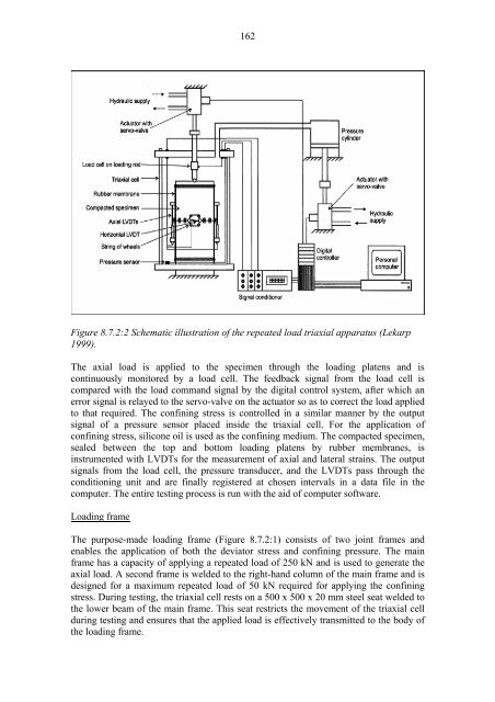
Figure 8.7.2:2 Schematic illustration <strong>of</strong> the repeated load triaxial apparatus (Lekarp<br />
1999).<br />
The axial load is applied to the specimen through the loading platens and is<br />
continuously monitored by a load cell. The feedback signal from the load cell is<br />
compared with the load command signal by the digital control system, after which an<br />
error signal is relayed to the servo-valve on the actuator so as to correct the load applied<br />
to that required. The confining stress is controlled in a similar manner by the output<br />
signal <strong>of</strong> a pressure sensor placed inside the triaxial cell. For the application <strong>of</strong><br />
confining stress, silicone oil is used as the confining medium. The compacted specimen,<br />
sealed between the top and bottom loading platens by rubber membranes, is<br />
instrumented with LVDTs for the measurement <strong>of</strong> axial and lateral strains. The output<br />
signals from the load cell, the pressure transducer, and the LVDTs pass through the<br />
conditioning unit and are finally registered at chosen intervals in a data file in the<br />
computer. The entire testing process is run with the aid <strong>of</strong> computer s<strong>of</strong>tware.<br />
Loading frame<br />
The purpose-made loading frame (Figure 8.7.2:1) consists <strong>of</strong> two joint frames and<br />
enables the application <strong>of</strong> both the deviator stress and confining pressure. The main<br />
frame has a capacity <strong>of</strong> applying a repeated load <strong>of</strong> 250 kN and is used to generate the<br />
axial load. A second frame is welded to the right-hand column <strong>of</strong> the main frame and is<br />
designed for a maximum repeated load <strong>of</strong> 50 kN required for applying the confining<br />
stress. During testing, the triaxial cell rests on a 500 x 500 x 20 mm steel seat welded to<br />
the lower beam <strong>of</strong> the main frame. This seat restricts the movement <strong>of</strong> the triaxial cell<br />
during testing and ensures that the applied load is effectively transmitted to the body <strong>of</strong><br />
the loading frame.