Deformation behaviour of railway embankment ... - Liikennevirasto
Deformation behaviour of railway embankment ... - Liikennevirasto
Deformation behaviour of railway embankment ... - Liikennevirasto

You also want an ePaper? Increase the reach of your titles
YUMPU automatically turns print PDFs into web optimized ePapers that Google loves.
167<br />
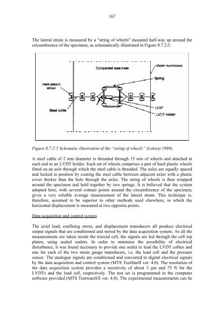
The lateral strain is measured by a "string <strong>of</strong> wheels" mounted half-way up around the<br />
circumference <strong>of</strong> the specimen, as schematically illustrated in Figure 8.7.2:5.<br />
Figure 8.7.2:5 Schematic illustration <strong>of</strong> the “string <strong>of</strong> wheels” (Lekarp 1999).<br />
A steel cable <strong>of</strong> 2 mm diameter is threaded through 15 sets <strong>of</strong> wheels and attached at<br />
each end to an LVDT holder. Each set <strong>of</strong> wheels comprises a pair <strong>of</strong> hard plastic wheels<br />
fitted on an axle through which the steel cable is threaded. The axles are equally spaced<br />
and locked in position by coating the steel cable between adjacent axles with a plastic<br />
cover thicker than the hole through the axles. The string <strong>of</strong> wheels is then wrapped<br />
around the specimen and held together by two springs. It is believed that the system<br />
adopted here, with several contact points around the circumference <strong>of</strong> the specimen,<br />
gives a very reliable average measurement <strong>of</strong> the lateral strain. This technique is,<br />
therefore, assumed to be superior to other methods used elsewhere, in which the<br />
horizontal displacement is measured at two opposite points.<br />
Data acquisition and control system<br />
The axial load, confining stress, and displacement transducers all produce electrical<br />
output signals that are conditioned and stored by the data acquisition system. As all the<br />
measurements are taken inside the triaxial cell, the signals are led through the cell top<br />
platen, using sealed outlets. In order to minimise the possibility <strong>of</strong> electrical<br />
disturbance, it was found necessary to provide one outlet to lead the LVDT cables and<br />
one for each <strong>of</strong> the two strain gauge transducers, i.e. the load cell and the pressure<br />
sensor. The analogue signals are conditioned and converted to digital electrical signals<br />
by the data acquisition and control system (MTS TestStarII ver. 4.0). The resolution <strong>of</strong><br />
the data acquisition system provides a sensitivity <strong>of</strong> about 3 µm and 75 N for the<br />
LVDTs and the load cell, respectively. The test set is programmed in the computer<br />
s<strong>of</strong>tware provided (MTS TestwareSX ver. 4.0). The experimental measurements can be