Radar Technology for Level Gauging - Krohne
Radar Technology for Level Gauging - Krohne
Radar Technology for Level Gauging - Krohne

You also want an ePaper? Increase the reach of your titles
YUMPU automatically turns print PDFs into web optimized ePapers that Google loves.
3. <strong>Radar</strong>-Füllstandsmesssysteme<br />
3.6 FMCW radar<br />
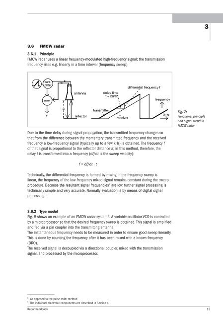
3.6.1 Principle<br />
FMCW radar uses a linear frequency-modulated high-frequency signal; the transmission<br />
frequency rises e.g. linearly in a time interval (frequency sweep).<br />
transmitter<br />
mixer<br />
f<br />
a<br />
antenna<br />
reflector<br />
Due to the time delay during signal propagation, the transmitted frequency changes so<br />
that from the difference between the momentary transmitted frequency and the received<br />
frequency a low-frequency signal (typically up to a few kHz) is obtained. The frequency f<br />
of that signal is proportional to the reflector distance a; in this method, there<strong>for</strong>e, the<br />
delay t is trans<strong>for</strong>med into a frequency (df/dt is the sweep velocity):<br />
f = df/dt · t<br />
transmitter<br />
delay time<br />
t = 2a/c<br />
Technically, the differential frequency is <strong>for</strong>med by mixing. If the frequency sweep is<br />
linear, the frequency of the low-frequency mixed signal remains constant during the sweep<br />
procedure. Because the resultant signal frequencies 8 are low, further signal processing is<br />
technically simple and very accurate. Normally evaluation is by means of digital signal<br />
processing.<br />
3.6.2 Type model<br />
Fig. 8 shows an example of an FMCW radar system 9 .A variable oscillator VCO is controlled<br />
byamicroprocessor so that the desired frequency sweep is obtained. This signal is amplified<br />
and fed via a pin coupler into the transmitting antenna.<br />
The instantaneous frequency needs to be measured in order to ensure good sweep linearity.<br />
This is done by counting the frequency after it has been mixed with a known frequency<br />
(DRO).<br />
The received signal is decoupled via a directional coupler, mixed with the transmission<br />
signal, and processed by the microprocessor.<br />
8 As opposed to the pulse radar method<br />
9 The individual electronic components are described in Section 4.<br />
receiver<br />
differential frequency f<br />
frequency<br />
Fig. 7:<br />
Functional principle<br />
and signal trend in<br />
FMCW radar<br />
<strong>Radar</strong> handbook 13<br />
time<br />
3