Radar Technology for Level Gauging - Krohne
Radar Technology for Level Gauging - Krohne
Radar Technology for Level Gauging - Krohne

Create successful ePaper yourself
Turn your PDF publications into a flip-book with our unique Google optimized e-Paper software.
4.4 Line transmission<br />
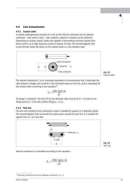
4.4.1 Coaxial cable<br />
A coaxial cable generally consists of a wire as the internal conductor and an external<br />
conductor – wire mesh or tube – with synthetic material in between as the dielectric.<br />
Depending on quality, coaxial cables are capable of transmitting electrical signals from<br />
direct current up to high-frequency waves of approx. 20 GHz. The electromagnetic field<br />
is only <strong>for</strong>med inside the cable, so the coaxial cable is a low-radiation type.<br />
The natural impedance Z L is an important parameter of a transmission line. It describes the<br />
ratio between voltages and currents in the individual waves on the line, and is calculated <strong>for</strong><br />
the coaxial cable according to the equation 14 :<br />
To design a "standard" line with 50 Ω, the diameter ratio must be D/d = 2.3 with an air<br />
filling and D/d = 3.35 with a Teflon filling (ε r = 2.1).<br />
4.4.2 Twin line<br />
The twin line consists of two conductors routed in parallel by spacers or a dielectric jacket.<br />
The electromagnetic field surrounds the entire space around the twin line. It is suitable <strong>for</strong><br />
signals from d.c. to a few GHz.<br />
2 wires<br />
14 Assuming a lossless line and non-magnetic environment (µr = 1)<br />
outer conductor<br />
dielectric<br />
inner conductor<br />
Natural impedance is calculated according to the equation:<br />
dielectric<br />
Fig. 12:<br />
Coaxial cable<br />
Fig. 13:<br />
Twin line<br />
<strong>Radar</strong> handbook 19<br />
4