Radar Technology for Level Gauging - Krohne
Radar Technology for Level Gauging - Krohne
Radar Technology for Level Gauging - Krohne

Create successful ePaper yourself
Turn your PDF publications into a flip-book with our unique Google optimized e-Paper software.
Also taking into account the equation <strong>for</strong> antenna gain G 1 (Section 5.2), and atmospheric<br />
attenuation α and a reflection factor R of the reflecting surface (see Section 7), we obtain<br />
the following interrelationships:<br />
A significant point is that the received power decreases with increasing distance a. Where<br />
a level measuring system is used in a large-area tank, equation (a) should be applied by<br />
approximation: the signal decreases to the square of a. Where extremely tall tanks or interference<br />
reflections from small internals are involved, it is better to use equation (b):<br />
decrease with the 4th power of a.<br />
In both cases, however, there is the same proportional dependence 25 on antenna diameter<br />
D and wavelength λ or transmission frequency f:<br />
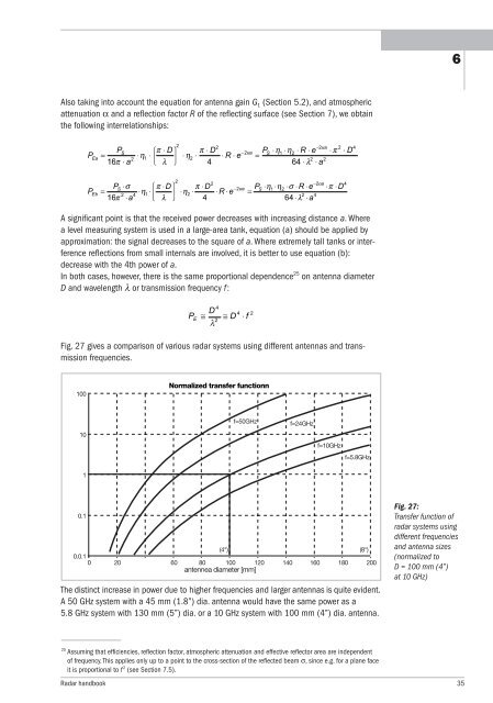
Fig. 27 gives a comparison of various radar systems using different antennas and transmission<br />
frequencies.<br />
100<br />
10<br />
1<br />
0.1<br />
Normalized transfer functionn<br />
f=50GHz f=24GHz<br />
f=10GHz<br />
f=5.8GHz<br />
(4") (8")<br />
0.0.1<br />
0 20 60 80 100 120 140 160 180 200<br />
antennea diameter [mm]<br />
The distinct increase in power due to higher frequencies and larger antennas is quite evident.<br />
A 50 GHz system with a 45 mm (1.8”) dia. antenna would have the same power as a<br />
5.8 GHz system with 130 mm (5”) dia. or a 10 GHz system with 100 mm (4”) dia. antenna.<br />
25 Assuming that efficiencies, reflection factor, atmospheric attenuation and effective reflector area are independent<br />
of frequency. This applies only up to a point to the cross-section of the reflected beam σ, since e.g. <strong>for</strong> a plane face<br />
it is proportional to f 2 (see Section 7.5).<br />
<strong>Radar</strong> handbook 35<br />
6<br />
Fig. 27:<br />
Transfer function of<br />
radar systems using<br />
different frequencies<br />
and antenna sizes<br />
(normalized to<br />
D = 100 mm (4”)<br />
at 10 GHz)