Radar Technology for Level Gauging - Krohne
Radar Technology for Level Gauging - Krohne
Radar Technology for Level Gauging - Krohne

Create successful ePaper yourself
Turn your PDF publications into a flip-book with our unique Google optimized e-Paper software.
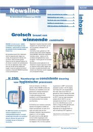
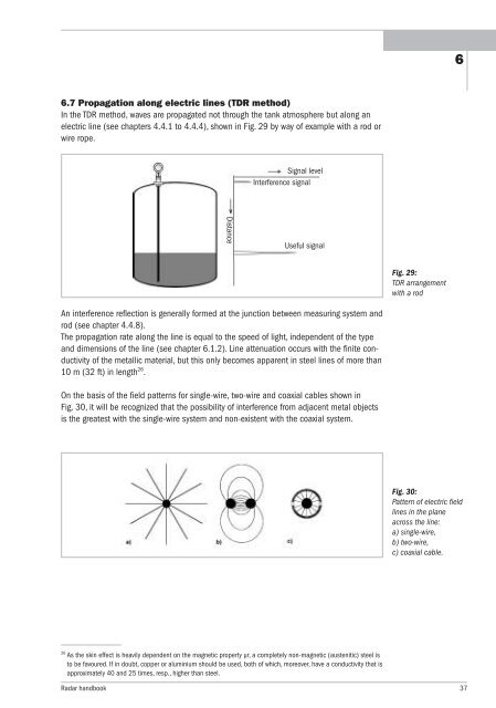
6.7 Propagation along electric lines (TDR method)<br />
In the TDR method, waves are propagated not through the tank atmosphere but along an<br />
electric line (see chapters 4.4.1 to 4.4.4), shown in Fig. 29 by way of example with a rod or<br />
wire rope.<br />
An interference reflection is generally <strong>for</strong>med at the junction between measuring system and<br />
rod (see chapter 4.4.8).<br />
The propagation rate along the line is equal to the speed of light, independent of the type<br />
and dimensions of the line (see chapter 6.1.2). Line attenuation occurs with the finite conductivity<br />
of the metallic material, but this only becomes apparent in steel lines of more than<br />
10 m (32 ft) in length 26 .<br />
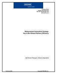
On the basis of the field patterns <strong>for</strong> single-wire, two-wire and coaxial cables shown in<br />
Fig. 30, it will be recognized that the possibility of interference from adjacent metal objects<br />
is the greatest with the single-wire system and non-existent with the coaxial system.<br />
26 As the skin effect is heavily dependent on the magnetic property µr, a completely non-magnetic (austenitic) steel is<br />
to be favoured. If in doubt, copper or aluminium should be used, both of which, moreover, have a conductivity that is<br />
approximately 40 and 25 times, resp., higher than steel.<br />
Distance<br />
Signal level<br />
Interference signal<br />
Useful signal<br />
Fig. 29:<br />
TDR arrangement<br />
with a rod<br />
<strong>Radar</strong> handbook 37<br />
6<br />
Fig. 30:<br />
Pattern of electric field<br />
lines in the plane<br />
across the line:<br />
a) single-wire,<br />
b) two-wire,<br />
c) coaxial cable.