Radar Technology for Level Gauging - Krohne
Radar Technology for Level Gauging - Krohne
Radar Technology for Level Gauging - Krohne

You also want an ePaper? Increase the reach of your titles
YUMPU automatically turns print PDFs into web optimized ePapers that Google loves.
3. <strong>Radar</strong>-Füllstandsmesssysteme<br />
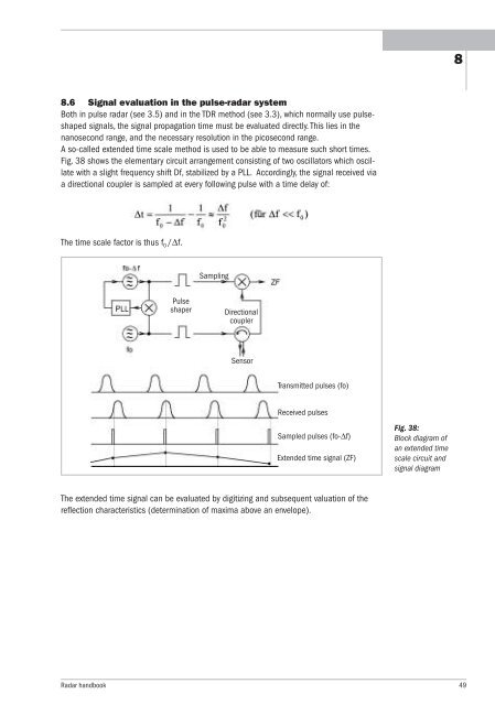
8.6 Signal evaluation in the pulse-radar system<br />
Both in pulse radar (see 3.5) and in the TDR method (see 3.3), which normally use pulseshaped<br />
signals, the signal propagation time must be evaluated directly. This lies in the<br />
nanosecond range, and the necessary resolution in the picosecond range.<br />
A so-called extended time scale method is used to be able to measure such short times.<br />
Fig. 38 shows the elementary circuit arrangement consisting of two oscillators which oscillate<br />
with a slight frequency shift Df, stabilized by a PLL. Accordingly, the signal received via<br />
a directional coupler is sampled at every following pulse with a time delay of:<br />
The time scale factor is thus f 0 /∆f.<br />
Sampling<br />
Pulse<br />
shaper Directional<br />
coupler<br />
Sensor<br />
Transmitted pulses (fo)<br />
Received pulses<br />
Sampled pulses (fo-∆f)<br />
Extended time signal (ZF)<br />
The extended time signal can be evaluated by digitizing and subsequent valuation of the<br />
reflection characteristics (determination of maxima above an envelope).<br />
Fig. 38:<br />
Block diagram of<br />
an extended time<br />
scale circuit and<br />
signal diagram<br />
<strong>Radar</strong> handbook 49<br />
8