Radar Technology for Level Gauging - Krohne
Radar Technology for Level Gauging - Krohne
Radar Technology for Level Gauging - Krohne

Create successful ePaper yourself
Turn your PDF publications into a flip-book with our unique Google optimized e-Paper software.
3. <strong>Radar</strong>-Füllstandsmesssysteme<br />
Typical values <strong>for</strong> antenna efficiency h 1 are approx. 0.5 - 0.8. Due to reciprocity 17 a gain G 2<br />
is imputed to a receiving antenna that is generally equal to the transmission G 1:<br />
received power of antenna in a planar wave field (optimally aligned)<br />
G2 =<br />
received power on an ideal isotropic radiator<br />
The following correlation with the effective receiving area AE is given by:<br />
5.3 Radiation angle<br />
A characteristic quantity <strong>for</strong> describing the directional effect is the radiation angle or halfvalue<br />
width. This is defined as the cone angle at whose edge the power density is 3 dB<br />
below the maximum power density (i.e. at the edge of this lobe the power density is half<br />
the size it is in the middle).<br />
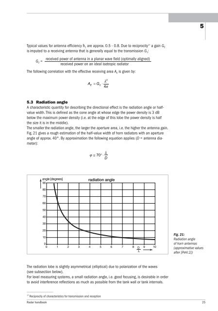
The smaller the radiation angle, the larger the aperture area, i.e. the higher the antenna gain.<br />
Fig. 21 gives a rough estimation of the half-value width of horn radiators with an aperture<br />
angle of approx. 40°. By approximation the following equation applies (D = antenna diameter):<br />
angle [degrees]<br />
90<br />
80<br />
70<br />
60<br />
50<br />
40<br />
30<br />
20<br />
10<br />
The radiation lobe is slightly asymmetrical (elliptical) due to polarization of the waves<br />
(see subsection below).<br />
For level measuring systems, a small radiation angle, i.e. good focusing, is desirable in order<br />
to avoid interference reflections as much as possible from the tank wall or tank internals.<br />
17 Reciprocity of characteristics <strong>for</strong> transmission and reception<br />
radiation angle<br />
0<br />
0 1 2 3 4 5 6 7 8 D<br />
λ<br />
9 10<br />
<strong>Radar</strong> handbook 25<br />
5<br />
Fig. 21:<br />
Radiation angle<br />
of horn antennas<br />
(approximative values<br />
after [Pehl.2])