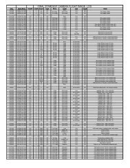
MISSION PLAN - PDS Small Bodies Node
MISSION PLAN - PDS Small Bodies Node
MISSION PLAN - PDS Small Bodies Node

Create successful ePaper yourself
Turn your PDF publications into a flip-book with our unique Google optimized e-Paper software.
The spacecraft’s trajectory and required cruise attitude history dictates the ACS<br />
perturbation due to limit cycling. The main source of attitude offset is the presence of<br />
solar torque which depends on the solar range and the spacecraft attitude with respect to<br />
the sun. The magnitude of the solar torque and the deadband within which the spacecraft<br />
attitude is controlled dictates the frequency at which the ACS thrusters are fired and the<br />
corresponding magnitude of the ACS perturbation. The direction of the ACS force, in<br />
the case of limit cycling, is parallel to the planned spacecraft +z-axis direction. The<br />
forces in the other two axis are assumed to cancel out on average.<br />
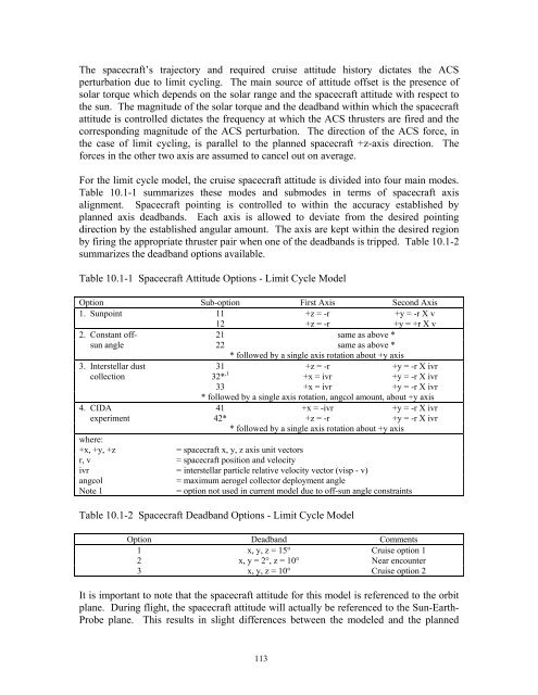
For the limit cycle model, the cruise spacecraft attitude is divided into four main modes.<br />
Table 10.1-1 summarizes these modes and submodes in terms of spacecraft axis<br />
alignment. Spacecraft pointing is controlled to within the accuracy established by<br />
planned axis deadbands. Each axis is allowed to deviate from the desired pointing<br />
direction by the established angular amount. The axis are kept within the desired region<br />
by firing the appropriate thruster pair when one of the deadbands is tripped. Table 10.1-2<br />
summarizes the deadband options available.<br />
Table 10.1-1 Spacecraft Attitude Options - Limit Cycle Model<br />
Option Sub-option First Axis Second Axis<br />
1. Sunpoint 11 +z = -r +y = -r X v<br />
12 +z = -r +y = +r X v<br />
2. Constant off- 21 same as above *<br />
sun angle 22 same as above *<br />
* followed by a single axis rotation about +y axis<br />
3. Interstellar dust 31 +z = -r +y = -r X ivr<br />
collection 32* ,1 +x = ivr +y = -r X ivr<br />
33 +x = ivr +y = -r X ivr<br />
* followed by a single axis rotation, angcol amount, about +y axis<br />
4. CIDA 41 +x = -ivr +y = -r X ivr<br />
experiment 42* +z = -r +y = -r X ivr<br />
* followed by a single axis rotation about +y axis<br />
where:<br />
+x, +y, +z<br />
= spacecraft x, y, z axis unit vectors<br />
r, v = spacecraft position and velocity<br />
ivr = interstellar particle relative velocity vector (visp - v)<br />
angcol<br />
= maximum aerogel collector deployment angle<br />
Note 1<br />
= option not used in current model due to off-sun angle constraints<br />
Table 10.1-2 Spacecraft Deadband Options - Limit Cycle Model<br />
Option Deadband Comments<br />
1 x, y, z = 15° Cruise option 1<br />
2 x, y = 2°, z = 10° Near encounter<br />
3 x, y, z = 10° Cruise option 2<br />
It is important to note that the spacecraft attitude for this model is referenced to the orbit<br />
plane. During flight, the spacecraft attitude will actually be referenced to the Sun-Earth-<br />
Probe plane. This results in slight differences between the modeled and the planned<br />
113