MISSION PLAN - PDS Small Bodies Node
MISSION PLAN - PDS Small Bodies Node
MISSION PLAN - PDS Small Bodies Node

You also want an ePaper? Increase the reach of your titles
YUMPU automatically turns print PDFs into web optimized ePapers that Google loves.
where:<br />
n *<br />
= thruster pulse frequency (1/s) τ s*<br />
= solar torque (x, y axis) (Nm)<br />
θ s<br />
= z-axis off-sun angle, l *<br />
= effective thruster moment arms<br />
(m),<br />
attitude plan dependent<br />
including effect of thruster cant<br />
I **<br />
= mass moments of inertia (kgm 2 ) db *<br />
= deadband limits (radians)<br />
= solar range (AU)<br />
R ***<br />
These equations decouple the motion in each of the spacecraft axis to facilitate the<br />
modeling process. Notice that the motion about the y axis of the spacecraft is driven<br />
primarily by the influence of the solar torque, while the solar torque components in the<br />
spacecraft z-axis is relatively small and ignored. The degree to which motion about the x<br />
axis is influenced by solar torque is determined by the solar range history of the mission.<br />
Near the sun (R≈Rmin), solar torque is the driving force behind the motion. Far from the<br />
sun (R≈Rmax), the influence of solar torque is minimal and represents steady state or<br />
pure limit cycling.<br />
The thruster pulse frequencies are then combined with the minimum impulse bit and<br />
attitude information to produce an average ACS force and corresponding acceleration.<br />
An average mass flow rate is also calculated to keep track of the change in the mass of<br />
the spacecraft due to the ACS activity. These values are calculated via the following<br />
equations.<br />
"<br />
f = f bit<br />
n T<br />
"<br />
k<br />
"<br />
a = "<br />
f / m<br />
m Ý = f n bit T<br />
Isp acs<br />
g<br />
where:<br />
"<br />
f<br />
"<br />
= ACS force vector (m/s)<br />
a = ACS acceleration vector (m/s 2 )<br />
Ým = mass flow rate (kg/s) Isp acs<br />
= ACS thruster specific impulse (s)<br />
g = gravity at Earth’s surface (m/s 2 "<br />
) k<br />
= unit vector in the direction of<br />
+z axis<br />
Deterministic mass decrements due to deterministic maneuvers and ACS burns are also<br />
included in the trajectory optimization code.<br />
10.1.3 Model Parameters and Characteristics<br />
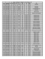
The attitude schedule and ACS force model parameters used for the data contained herein<br />
are summarized in Tables 10.1-3 and 10.1-4. The resultant total thruster pulse frequency,<br />
mass flow rate, acceleration and acceleration direction are illustrated in Figures 10.1-1<br />
thru 10.1-4.<br />
Table 10.1-3 Spacecraft Attitude Profile - Limit Cycle Model<br />
115