

TELE-X - a Satellite System for TV and Data Communication ...
TELE-X - a Satellite System for TV and Data Communication ...
TELE-X - a Satellite System for TV and Data Communication ...

You also want an ePaper? Increase the reach of your titles
YUMPU automatically turns print PDFs into web optimized ePapers that Google loves.
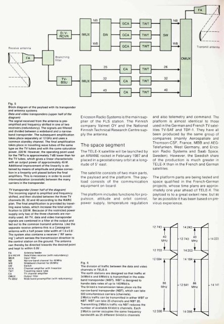
Fig. 5<br />
Block diagram of the payload with its transponder<br />
<strong>and</strong> antenna systems<br />
<strong>Data</strong> <strong>and</strong> video transponders (upper half of the<br />
diagram)<br />
The signal received from the antenna is preamplified<br />
<strong>and</strong> frequency shifted in one of two<br />
receivers (redundancy). The signals are filtered<br />
<strong>and</strong> divided between a wideb<strong>and</strong> <strong>and</strong> a narrowb<strong>and</strong><br />
transponder. The subsequent amplification<br />
takes place separately at 12 GHz <strong>and</strong> uses a<br />
common st<strong>and</strong>by channel. The final amplification<br />
takes place in travelling wave tubes of the same<br />
type as the <strong>TV</strong> tubes <strong>and</strong> with the same saturation<br />
power, 220 W. However, the operating point used<br />
<strong>for</strong> the TWTs is approximately 7dB lower than <strong>for</strong><br />
the <strong>TV</strong> tubes, which gives a linear characteristic<br />
with an output power of approximately 45 W.<br />
Additional improvement of the linearity is obtained<br />
by means of amplitude <strong>and</strong> phase correction<br />
in a linearity unit placed be<strong>for</strong>e the final<br />
amplifiers. This is necessary in order to avoid<br />
intermodulation (crosstalk) between the many<br />
carriers in the transponder.<br />
<strong>TV</strong> transponder (lower half of the diagram)<br />
The incoming signal is amplified <strong>and</strong> frequency<br />
shifted, <strong>and</strong> then divided between the three <strong>TV</strong><br />
channels 26, 32 <strong>and</strong> 40 according to the WARC<br />
plan. The final amplification is provided by travelling<br />
wave tubes, which increase the total amplification<br />
to 220 W. Because of the restricted power<br />
supply only two of the three channels are normally<br />
used. All <strong>TV</strong>, data <strong>and</strong> video transponder<br />
signals are combined in a filter at the output <strong>and</strong><br />
fed out to the common transmit antenna. Like the<br />
separate receive antenna this is a Cassegrain<br />
antenna with a half power lobe width of 1.6x0.8 .<br />
The system also contains a receiver ("RF sensing")<br />
which senses the transmission direction to<br />
the control station on the ground. The antenna<br />
can thereby be directed towards the desired point<br />
<strong>and</strong> kept to within 0.05 .<br />
Ericsson Radio <strong>System</strong>s isthe main supplier<br />
of the FLS station The Finnish<br />
company Valmet OY <strong>and</strong> the National<br />
Finnish Technical Research Centre supply<br />
the antenna.<br />
The space segment<br />
The <strong>TELE</strong>-X satellite will be launched by<br />
an ARIANE rocket in February 1987 <strong>and</strong><br />
placed in a geostationary orbit at a longitude<br />
of 5 C east.<br />
The satellite consists of two main parts,<br />
the payload <strong>and</strong> the plat<strong>for</strong>m The payload<br />
consists of the communication<br />
equipment on board.<br />
The plat<strong>for</strong>m includes functions <strong>for</strong> propulsion,<br />
attitude <strong>and</strong> orbit control,<br />
power supply, temperature regulation<br />
<strong>and</strong> also telemetry <strong>and</strong> comm<strong>and</strong>. The<br />
plat<strong>for</strong>m is almost identical to those<br />
used in the German <strong>and</strong> French <strong>TV</strong> satellites<br />
<strong>TV</strong>-SAT <strong>and</strong> TDF-1. They have all<br />
been produced by the same group of<br />
companies (mainly Aerospatiale <strong>and</strong><br />
Thomson-CSF, France, MBB <strong>and</strong> AEG-<br />
Telefunken, West Germany, <strong>and</strong> Ericsson<br />
Radio <strong>System</strong>s <strong>and</strong> Saab Space,<br />
Sweden). However, the Swedish share<br />
of the production is much greater in<br />
<strong>TELE</strong>-X than in the French <strong>and</strong> German<br />
satellites.<br />
The plat<strong>for</strong>m parts are being tested <strong>and</strong><br />
space qualified in the French-German<br />
projects, whose time plans are approximately<br />
one year ahead of <strong>TELE</strong>-X. The<br />
payload is to a great extent new, but as<br />
far as possible it has been based on previous<br />
experience.<br />
FA<br />
D/V-RCVR<br />
IMUX<br />
NB<br />
WB<br />
SW<br />
GCA<br />
TWT<br />
CA<br />
OMUX<br />
<strong>TV</strong>-BSU<br />
Antenna feeder<br />
<strong>Data</strong>/Video receiver (with redundancy)<br />
Input filter<br />
Narrow-b<strong>and</strong> channel <strong>for</strong> 40 MHz<br />
Wideb<strong>and</strong> channel <strong>for</strong> 85 MHz<br />
Switch<br />
Channel amplifier with linearizer<br />
Travelling wave tube<br />
<strong>TV</strong> channel amplifier<br />
Output filter<br />
Wide-b<strong>and</strong> preamplifier (with reduncancy)<br />
Fig. 6<br />
The division of traffic between the data <strong>and</strong> video<br />
channels in <strong>TELE</strong>-X.<br />
The earth stations are designed so that traffic at<br />
34 Mbit s <strong>and</strong> 8 Mbit s is transmitted in the wideb<strong>and</strong><br />
transponder (WBT). WBT is designed to<br />
h<strong>and</strong>le data rates of up to 140Mbit/s.<br />
The 64kbit/s transmission takes place via the<br />
narrow-b<strong>and</strong> transponder (NBT), which can take<br />
500 simultaneous carriers (channels).<br />
2 Mbit/s traffic can be transmitted in either WBT or<br />
NBT. WBT can take 25 channels <strong>and</strong> NBT 20.<br />
Transmitting 2 Mbit/s traffic via NBT reduces the<br />
number of available 64kbit/s channels. Each<br />
2 Mbit/s carrier occupies the same frequency<br />
b<strong>and</strong>width as 25 different 64kbit/s channels


