

TELE-X - a Satellite System for TV and Data Communication ...
TELE-X - a Satellite System for TV and Data Communication ...
TELE-X - a Satellite System for TV and Data Communication ...

Create successful ePaper yourself
Turn your PDF publications into a flip-book with our unique Google optimized e-Paper software.
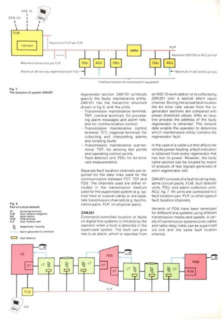
Fig. 7<br />
The structure of system 2AN201<br />
Fig. 8<br />
Part of a local network<br />
ET<br />
FLM<br />
WS<br />
PCM<br />
FLP<br />
Exchange terminal<br />
Fault location magazine<br />
Work station<br />
PCM terminal<br />
Fault location pair<br />
R. Regenerator housing<br />
regenerator section ZAN 101 printouts<br />
specify the faulty maintenance entity.<br />
ZAN 101 has the hierarchic structure<br />
shown in fig.6, with the units:<br />
- Transmission maintenance terminal,<br />
TMT, (central terminal), <strong>for</strong> processing<br />
alarm messages <strong>and</strong> alarm lists,<br />
<strong>and</strong> <strong>for</strong> communication control<br />
- Transmission maintenance control<br />
terminal, TCT, (regional terminal), <strong>for</strong><br />
collecting <strong>and</strong> interpreting alarms<br />
<strong>and</strong> locating faults<br />
- Transmission maintenance sub-terminal,<br />
TST, <strong>for</strong> sensing test points<br />
<strong>and</strong> operating control points<br />
- Fault detector unit, FDU, <strong>for</strong> bit error<br />
rate measurements.<br />
Separate fault location channels are required<br />
<strong>for</strong> the data links used <strong>for</strong> the<br />
communication between TCT, TST <strong>and</strong><br />
FDU. The channels used are either included<br />
in the transmission medium<br />
used <strong>for</strong> the supervised system (e.g. optical<br />
fibre or coaxial cable) or are separate<br />
transmission channels (e.g. fault location<br />
pairs, FLP, on physical pairs).<br />
ZAN 201<br />
Comm<strong>and</strong>-controlled location of faults<br />
on digital line systems is initiated by the<br />
operator when a fault is detected in the<br />
supervised system. The fault can give<br />
rise to an alarm, which is reported from<br />
an AXE 10 work station or is collected by<br />
ZAN 201 over a special alarm report<br />
channel. During the actual fault location<br />
the bit error rate values from the regenerator<br />
sections are compared with<br />
preset threshold values. After an iterative<br />
process the address of the faulty<br />
regenerator is obtained. The network<br />
data enable the operator to determine<br />
which maintenance entity contains the<br />
regenerator fault.<br />
In the case of a cable cut that affects the<br />
remote power feeding, a fault indication<br />
is obtained from every regenerator that<br />
has lost its power. However, the faulty<br />
cable section can be located by means<br />
of analysis of test signals generated at<br />
each regenerator site.<br />
ZAN 201 consists of a fault locating magazine<br />
(circuit pack), FLM, fault detector<br />
units, FDU, <strong>and</strong> alarm collection units,<br />
ACU, fig. 7. All units are connected to a<br />
fault location pair, FLP, or other types of<br />
fault location channels.<br />
Variants of FDU have been developed<br />
<strong>for</strong> different line systems using different<br />
transmission media <strong>and</strong> speeds. A variety<br />
of transmission systems (over cables<br />
<strong>and</strong> radio relay links) can be supervised<br />
via one <strong>and</strong> the same fault location<br />
channel.


