

TELE-X - a Satellite System for TV and Data Communication ...
TELE-X - a Satellite System for TV and Data Communication ...
TELE-X - a Satellite System for TV and Data Communication ...

Create successful ePaper yourself
Turn your PDF publications into a flip-book with our unique Google optimized e-Paper software.
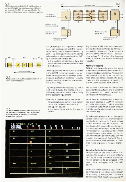
Fig. 5<br />
2 Mbit/s line system ZAD 2-6. The different parts<br />
are identified with the aid of addresses. Alarms<br />
are connected to ZAN101 <strong>and</strong> identified by the<br />
physical position in the alarm collection magazine<br />
Fig. 4<br />
Maintenance Entities, ME, in accordance with the<br />
CCITT recommendation<br />
Fig. 7<br />
The alarm display in AOM 101 is divided up so<br />
that each sector represents the transmission<br />
equipment either in a station or on a route<br />
between two stations<br />
The grouping of the supervised equipment<br />
is in accordance with the maintenance<br />
entity concept recommended by<br />
CCITT, i.e. the equipment is divided into<br />
independent maintenance entities, ME,<br />
fig. 4, which can consist of:<br />
- a line system consisting of two line<br />
terminals <strong>and</strong> intermediate repeaters<br />
- a multiplexer.<br />
Other equipment, which is not included<br />
in the CCITT recommendation, <strong>for</strong> example<br />
analog transmission equipment,<br />
pressure protection systems, security<br />
systems <strong>and</strong> fire detectors, are divided<br />
into similar MEs.<br />
Digital equipment is designed so that a<br />
fault that disturbs the traffic will normally<br />
only initiate an alarm in the faulty<br />
or the adjacent equipment.<br />
Each ME is identified with the aid of<br />
- its geographical position, i.e. a station<br />
or a route between two stations<br />
- the type of device<br />
- a numerical index within the type of<br />
device.<br />
Fig. 5 shows a 2 Mbit/s line system comprising<br />
two line terminals <strong>and</strong> three intermediate<br />
repeaters. Fig. 6 shows a<br />
printout of the network data. The examples<br />
in figs. 7-10 show what happens<br />
when a fault occurs in an intermediate<br />
repeater.<br />
Alarm processing<br />
ZAN 101 continuously scans the alarm<br />
status of all connected devices <strong>and</strong> initiates<br />
printouts of all alarms. For each ME<br />
the network data includes the seriousness<br />
of each alarm condition, the alarm<br />
class <strong>and</strong> the category <strong>for</strong> routing of<br />
alarms to the desired work station.<br />
Alarms from a device which has already<br />
been identified as faulty <strong>and</strong> alarms that<br />
are generated in connection with fault<br />
tracing can be suppressed.<br />
WhenZAN101 is connected to AOM 101<br />
the alarm display in AOM 101 receives<br />
an initial alarm report, which provides<br />
in<strong>for</strong>mation as to which station or route<br />
is initiating the alarm <strong>and</strong> how serious<br />
the fault is, fig. 7.<br />
By acknowledging the alarm the operator<br />
can then receive in<strong>for</strong>mation regarding<br />
the faulty system, fig. 8, <strong>and</strong> various<br />
traffic activities can be initiated. Depending<br />
on the circumstances the operator<br />
can then either try to locate the fault<br />
immediately or leave it until later. More<br />
detailed alarm in<strong>for</strong>mation can be obtained<br />
by means of comm<strong>and</strong>s, <strong>and</strong> will<br />
simplify the tracing of the fault. The alarm<br />
in<strong>for</strong>mation then received is of the<br />
type "loss of power", "loss of signal",<br />
etc.<br />
Locating faults in line systems<br />
The purpose of the fault location is to<br />
indicate the position <strong>and</strong> type of faulty<br />
devices in order to enable the maintenance<br />
personnel to be directed to the<br />
right place, equipped with the right<br />
spares.<br />
When an alarm occurs a fault location<br />
comm<strong>and</strong> is given either automatically<br />
or manually by the operator. The operator<br />
requests fault location by giving the


