
You also want an ePaper? Increase the reach of your titles
YUMPU automatically turns print PDFs into web optimized ePapers that Google loves.
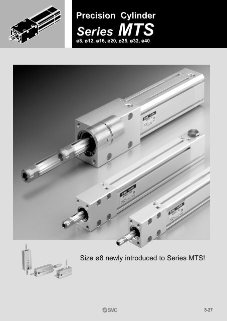
<strong>Precision</strong> <strong>Cylinder</strong><br />
<strong>Series</strong> <strong>MTS</strong><br />
ø8, ø12, ø16, ø20, ø25, ø32, ø40<br />
Size ø8 newly introduced to <strong>Series</strong> <strong>MTS</strong>!<br />
3-27
<strong>Precision</strong> <strong>Cylinder</strong> w<br />
<strong>Precision</strong> <strong>Cylinder</strong><br />
Non-rotating accuracy:<br />
0.1° or less<br />
(0.2° or less for ø8, within allowable torque values)<br />
<strong>MTS</strong>8<br />
Short mounting pitch: 15mm<br />
Small size ø8 introduced to series<br />
Rod through hole allows<br />
vacuum piping (order made)<br />
Lifting and transfer of small<br />
electronic parts is possible Piping is<br />
with short mounting pitch possible from<br />
two directions<br />
22<br />
15<br />
Uses new type compact<br />
auto switches (ø8 only)<br />
Two auto switches can be<br />
mounted even with the<br />
minimum 5mm stroke<br />
Mounting space reduced<br />
Two types of<br />
rod end configuration<br />
Standard: Rod end female threads<br />
Optional: Rod end male threads (using stud bolt)<br />
Auto switch capable<br />
on four sides<br />
(two sides for ø8)<br />
Three types of mounting possible<br />
Tapped holes<br />
Rod end female threads<br />
Rod end male threads<br />
Through holes<br />
Bottom mount Front mount Side mount (both sides)<br />
3-28<br />
(Side mounting is not possible for size ø8.)
ith Internal Guide Function<br />
<strong>Series</strong> <strong>MTS</strong><br />
Deflection:<br />
0.1mm or less<br />
(for <strong>MTS</strong>12-25, within allowable lateral load values)<br />
Reduced labour for design<br />
and assembly<br />
Applications<br />
• Picking and placing<br />
High precision mounting<br />
A<br />
• Transfer of work pieces<br />
0.1 A 0.1 A 0.1 A 0.1 A<br />
Parallelism of mounting surfaces (side, bottom) to rod: 0.1mm or less<br />
Squareness of mounting surface (front) to rod: 0.1mm or less<br />
Air cushion standardised<br />
(ø8 equipped with rubber bumper)<br />
Rear end lock type added<br />
to series (ø12 to ø40)<br />
• Positioning pins<br />
Sealing and durability equivalent to<br />
conventional round rod models have<br />
been achieved with a specially<br />
configured rod seal<br />
Stroke adjustment mechanism<br />
Order made specifications<br />
Stroke adjustment is possible on the rod extension side.<br />
Stroke adjustment range: 0 to 10mm (ø8)<br />
: 0 to 25mm (ø12 to ø40)<br />
<strong>Series</strong> variations<br />
Model<br />
<strong>MTS</strong>8<br />
<strong>MTS</strong>12<br />
<strong>MTS</strong>16<br />
<strong>MTS</strong>20<br />
<strong>MTS</strong>25<br />
<strong>MTS</strong>32<br />
<strong>MTS</strong>40<br />
Standard stroke (mm)<br />
5 10 15 20 25 30 50 75 100 125 150 175 200<br />
Rod end<br />
configuration<br />
Female<br />
threads<br />
(standard)<br />
Male<br />
threads<br />
(optional)<br />
Cushion<br />
Rubber bumper<br />
Air cushion<br />
End lock<br />
Options<br />
Rod Variable stroke<br />
through hole Extension adjustment<br />
3-29
<strong>Precision</strong><br />
<strong>Cylinder</strong><br />
Se ries <strong>MTS</strong><br />
ø8, ø12, ø16, ø20, ø25, ø32, ø40<br />
How to Order<br />
ø8<br />
ø12 to ø40<br />
<strong>MTS</strong> 20<br />
Bore size<br />
12mm<br />
16mm<br />
20mm<br />
25mm<br />
32mm<br />
40mm<br />
Port direction<br />
Standard piping type<br />
Axial piping type<br />
<strong>MTS</strong> 8 20 A90L<br />
12<br />
16<br />
20<br />
25<br />
32<br />
40<br />
Bore size<br />
8 8mm<br />
TF<br />
Thread Port<br />
(ø32,ø40)<br />
Rc(PT)<br />
TF G(PF)<br />
100<br />
Nil<br />
P<br />
A90L<br />
Auto switch type<br />
Number of auto switches<br />
Nil 2 pcs.<br />
S 1 pc.<br />
Nil Without auto switch<br />
∗ Refer to the table below for auto<br />
switch part numbers.<br />
For ø8 cylinders with auto switch, some auto<br />
switches cannot be mounted depending on piping<br />
direction and stroke size.<br />
Applicable auto switches<br />
Type<br />
Reed<br />
switch<br />
Solid<br />
state<br />
switch<br />
Special<br />
functions<br />
Diagnostic<br />
indication<br />
(2 colour<br />
indicator)<br />
Electrical<br />
entry<br />
Grommet<br />
Grommet<br />
Indicator<br />
light<br />
No<br />
Yes<br />
Yes<br />
<strong>Cylinder</strong> stroke (mm)<br />
Nil<br />
R<br />
Wiring<br />
(output)<br />
2 wire<br />
3 wire<br />
(NPN<br />
equiv.)<br />
3 wire<br />
(NPN)<br />
3 wire<br />
(PNP)<br />
2 wire<br />
3 wire<br />
(NPN)<br />
3 wire<br />
(PNP)<br />
End lock<br />
Without end lock<br />
With rear end lock<br />
Load voltage<br />
24V<br />
24V<br />
2 wire 12V<br />
∗ Lead wire length symbols 0.5m ........ Nil (Ex.) A93<br />
3m ......... L (Ex.) A93L<br />
5m ......... Z (Ex.) M9NWZ<br />
∗ Solid state auto switches marked with a "" are produced upon receipt of order.<br />
∗∗ D-F8 type auto switches are only applicable to ø8 cylinders.<br />
3-30<br />
DC<br />
5V<br />
12V<br />
AC<br />
Auto switch model<br />
Electrical entry direction<br />
Perpendicular In-line<br />
Lead wire length (m)<br />
0.5<br />
(Nil)<br />
3<br />
(L)<br />
A90V A90 <br />
12V 100V A93V A93<br />
5V<br />
5V<br />
12V<br />
12V<br />
5V<br />
12V<br />
100V<br />
or less<br />
A96V<br />
Rod end configuration<br />
A96<br />
Rod end female threads<br />
Rod end male threads<br />
<br />
<br />
M9NV M9N <br />
F8N ∗∗ <br />
M9PV<br />
M9BV<br />
M9NWV<br />
M9PWV<br />
M9BWV<br />
Nil<br />
M<br />
M9P<br />
M9B<br />
M9NW<br />
M9PW<br />
M9BW<br />
<br />
<br />
<br />
<br />
<br />
<br />
<br />
<br />
F8P ∗∗ <br />
<br />
F8B ∗∗ <br />
<br />
<br />
<br />
5<br />
(Z)<br />
<br />
<br />
<br />
<br />
<br />
<br />
<br />
<br />
<br />
Applicable<br />
load<br />
IC<br />
circuit<br />
IC<br />
circuit<br />
IC<br />
circuit<br />
Relay,<br />
PLC<br />
Relay,<br />
PLC
<strong>Precision</strong> <strong>Cylinder</strong> <strong>Series</strong> <strong>MTS</strong><br />
Specifications<br />
Bore size (mm)<br />
Spline rod size (mm)<br />
Fluid<br />
Min. operating<br />
pressure<br />
Maximum operating pressure<br />
Proof pressure<br />
Ambient and fluid temperature<br />
Bearing type<br />
Cushion<br />
Effective cushion length (mm)<br />
Lubrication<br />
Auto switches<br />
Stroke tolerance<br />
Non-rotating accuracy<br />
Port size<br />
Without end lock<br />
With end lock ∗<br />
Piston Speed<br />
8<br />
4<br />
0.15MPa<br />
—<br />
Rubber<br />
bumper<br />
—<br />
Reed switch:<br />
D-A9<br />
Solid state switch:<br />
D-F9<br />
D-F8<br />
0.2° or less<br />
(within allowable<br />
torque values)<br />
M3<br />
12<br />
6<br />
16<br />
8<br />
0.12MPa<br />
0.17MPa<br />
20<br />
10<br />
Air<br />
0.7MPa<br />
1.0MPa<br />
–10 to 60°C (with no freezing)<br />
Ball spline<br />
Air cushion<br />
Non-lube<br />
+1.0<br />
0<br />
mm<br />
∗ Except for lock unit: 0.12MPa for ø12 and 16; 0.10MPa for ø20 to 40<br />
25<br />
13<br />
0.1MPa<br />
0.15MPa<br />
Reed switch: D-A9<br />
Solid state switch: D-F9<br />
32<br />
16<br />
40<br />
9 10 11 12 17 17<br />
M5<br />
0.1° or less (within allowable torque values)<br />
20<br />
M5 M5 M5 1/8 1/8<br />
Bore size (mm)<br />
Piston speed (mm/s)<br />
Allowable kinetic energy J<br />
8<br />
50 to 500<br />
0.02<br />
12<br />
0.19<br />
16<br />
0.32<br />
20 25<br />
50 to 800<br />
0.55 0.78<br />
32<br />
1.6<br />
40<br />
2.8<br />
End Lock Specifications<br />
Standard Strokes<br />
Bore size (mm)<br />
8<br />
12, 16<br />
20, 25, 32, 40<br />
Standard stroke (mm)<br />
5, 10, 15, 20, 25, 30<br />
25, 50, 75, 100<br />
25, 50, 75, 100, 125,<br />
150, 175, 200<br />
∗ Strokes other than the above are produced<br />
upon receipt of order.<br />
Stud Bolt Part Numbers<br />
Bore size (mm)<br />
Part no.<br />
8<br />
MT-S8<br />
12<br />
MT-S12<br />
16<br />
MT-S16<br />
20<br />
MT-S20<br />
25<br />
MT-S25<br />
32<br />
MT-S32<br />
40<br />
MT-S40<br />
∗ Replacement parts for rod end male threads.<br />
∗ Rod end nuts are included.<br />
Bore size (mm)<br />
Lock position<br />
Holding force (max.) N<br />
Backlash<br />
Manual unlocking<br />
12<br />
29<br />
Theoretical Output<br />
Bore size<br />
(mm)<br />
8<br />
12<br />
16<br />
20<br />
25<br />
32<br />
40<br />
Weights<br />
Model<br />
<strong>MTS</strong>8<br />
<strong>MTS</strong>12<br />
<strong>MTS</strong>16<br />
<strong>MTS</strong>20<br />
<strong>MTS</strong>25<br />
<strong>MTS</strong>32<br />
<strong>MTS</strong>40<br />
5<br />
36<br />
—<br />
—<br />
—<br />
—<br />
—<br />
—<br />
Operating<br />
direction<br />
10<br />
40<br />
—<br />
—<br />
—<br />
—<br />
—<br />
—<br />
OUT<br />
IN<br />
OUT<br />
IN<br />
OUT<br />
IN<br />
OUT<br />
IN<br />
OUT<br />
IN<br />
OUT<br />
IN<br />
OUT<br />
IN<br />
15<br />
44<br />
—<br />
—<br />
—<br />
—<br />
—<br />
—<br />
Piston area<br />
(mm²)<br />
16<br />
53<br />
20 25<br />
Rear end only<br />
82 125<br />
1mm<br />
Non-locking type only<br />
32<br />
211<br />
Operating pressure (MPa)<br />
0.2 0.3 0.4 0.5 0.6 0.7<br />
50<br />
37<br />
113<br />
84<br />
201<br />
150<br />
314<br />
235<br />
490<br />
358<br />
804<br />
603<br />
1,256<br />
942<br />
10<br />
8<br />
23<br />
17<br />
40<br />
30<br />
63<br />
47<br />
98<br />
72<br />
161<br />
121<br />
251<br />
188<br />
15<br />
11<br />
34<br />
25<br />
60<br />
45<br />
94<br />
71<br />
147<br />
107<br />
241<br />
181<br />
377<br />
283<br />
20<br />
15<br />
45<br />
34<br />
80<br />
60<br />
126<br />
94<br />
196<br />
143<br />
322<br />
241<br />
502<br />
377<br />
25<br />
19<br />
57<br />
42<br />
101<br />
75<br />
157<br />
118<br />
245<br />
179<br />
402<br />
302<br />
628<br />
471<br />
30<br />
22<br />
68<br />
50<br />
121<br />
90<br />
188<br />
141<br />
294<br />
215<br />
482<br />
362<br />
754<br />
565<br />
35<br />
26<br />
79<br />
59<br />
141<br />
105<br />
220<br />
165<br />
343<br />
251<br />
563<br />
422<br />
879<br />
659<br />
Caution Do not apply a load that is 50% or more of the theoretical output.<br />
20<br />
48<br />
—<br />
—<br />
—<br />
—<br />
—<br />
—<br />
25<br />
52<br />
138<br />
186<br />
350<br />
487<br />
918<br />
1,420<br />
Standard stroke (mm)<br />
30<br />
56<br />
—<br />
—<br />
—<br />
—<br />
—<br />
—<br />
50<br />
—<br />
157<br />
222<br />
400<br />
547<br />
1,000<br />
1,533<br />
75<br />
—<br />
175<br />
258<br />
450<br />
608<br />
1,083<br />
1,645<br />
100<br />
—<br />
194<br />
294<br />
500<br />
669<br />
1,165<br />
1,758<br />
125<br />
—<br />
—<br />
—<br />
549<br />
729<br />
1,247<br />
1,870<br />
150<br />
—<br />
—<br />
—<br />
599<br />
790<br />
1,330<br />
1,983<br />
175<br />
—<br />
—<br />
—<br />
649<br />
851<br />
1,412<br />
2,095<br />
200<br />
—<br />
—<br />
—<br />
699<br />
912<br />
1,495<br />
2,208<br />
40<br />
329<br />
End lock<br />
additional<br />
weight<br />
—<br />
29<br />
34<br />
42<br />
55<br />
90<br />
133<br />
(N)<br />
(g)<br />
3-31
<strong>Series</strong> <strong>MTS</strong><br />
Construction<br />
Basic type<br />
ø8<br />
ø12 to ø40<br />
Rod cross section<br />
for ø12, ø16, ø20,<br />
and ø25<br />
Rod cross section<br />
for ø32 and ø40<br />
With end lock<br />
ø12 to ø40<br />
Parts list<br />
No.<br />
1<br />
2<br />
3<br />
4<br />
5<br />
6<br />
7<br />
8<br />
9<br />
10<br />
11<br />
12<br />
13<br />
14<br />
Description<br />
Rod cover<br />
Head cover<br />
<strong>Cylinder</strong> tube<br />
Piston<br />
Spacer for switch type<br />
Spline rod<br />
Cushion bolt<br />
End lock bolt<br />
Collar<br />
Spline nut<br />
Cushion needle<br />
Cap<br />
Lock piston<br />
Lock spring<br />
Material<br />
Aluminium alloy<br />
Aluminium alloy<br />
Aluminium alloy<br />
Aluminium alloy<br />
Aluminium alloy<br />
Stainless steel<br />
Carbon steel<br />
Stainless steel<br />
Carbon steel<br />
Carbon steel<br />
Aluminium alloy<br />
Carbon steel<br />
Bronze alloy<br />
Carbon steel<br />
Steel wire<br />
Qty.<br />
Note<br />
1 Clear anodized<br />
1 Clear anodized<br />
1 Hard anodized<br />
1<br />
Chromated<br />
1<br />
Chromated<br />
1 ø8: Quenched<br />
1 ø12 to ø40: Quenched/Hard chrome plated<br />
1<br />
ø8 to ø16<br />
1 ø20 to ø40: Zinc chromated<br />
1 Quenched/Zinc chromated<br />
1<br />
Chromated<br />
1<br />
2<br />
Nickel plated<br />
1<br />
Nickel plated<br />
1 Quenched/Hard chrome plated<br />
1 Zinc chromated<br />
No.<br />
15<br />
16<br />
17<br />
18<br />
19<br />
20<br />
21<br />
22<br />
23<br />
24<br />
25<br />
26<br />
27<br />
28<br />
29<br />
Description<br />
Bumper<br />
Key<br />
C type snap ring for hole<br />
Magnet<br />
Plug<br />
Hexagon socket head set screw<br />
Piston seal<br />
Spline seal<br />
Collar gasket<br />
Tube gasket<br />
Piston gasket<br />
Cushion seal<br />
Needle gasket<br />
Piston seal for lock<br />
Cap gasket<br />
Material<br />
Urethane<br />
Carbon steel<br />
Carbon tool steel<br />
Alloyed steel<br />
Alloyed steel<br />
NBR<br />
NBR<br />
NBR<br />
NBR<br />
NBR<br />
Urethane<br />
NBR<br />
NBR<br />
NBR<br />
Qty. Note<br />
2<br />
ø8<br />
1 ø12 to ø40<br />
1<br />
2 ø8: Nickel plated<br />
1 ø12 to ø40: Nickel plated<br />
1<br />
3 Nickel plated<br />
1 Black zinc chromated<br />
1<br />
1 Rod seal for ø8<br />
1<br />
1<br />
ø8<br />
2 ø12 to ø40<br />
1<br />
2<br />
2<br />
1<br />
1<br />
3-32
Dimensions/ø8<br />
<strong>Precision</strong> <strong>Cylinder</strong> <strong>Series</strong> <strong>MTS</strong><br />
<strong>MTS</strong>8<br />
Basic type<br />
+0.035<br />
ø4 +0.025<br />
9 ±0.2<br />
2-M3<br />
Effective length 5<br />
12<br />
22<br />
16 ±0.2<br />
9<br />
±0.2<br />
10 15 ±0.2<br />
4-M3 effective length 5<br />
2-M3<br />
(port size for axial piping type<br />
<strong>MTS</strong>8-P)<br />
M2.5 12<br />
5ø4 +0.025<br />
41 + Stroke<br />
9<br />
53 + Stroke<br />
15<br />
Width across flats 3.5<br />
23 9<br />
6.5<br />
3.5<br />
2-M3<br />
(port size)<br />
4.5 4.5<br />
Rod end male threads<br />
Width across flats 3.5<br />
M3<br />
+0.035<br />
ø3.9<br />
M3<br />
7<br />
6.4<br />
8 4<br />
24<br />
2.4<br />
5.5<br />
Stud bolt part number: MT-S8<br />
Rod end nut part number: NTJ-006A<br />
3-33
<strong>Series</strong> <strong>MTS</strong><br />
Dimensions/ø12<br />
<strong>MTS</strong>12<br />
Basic type<br />
10 ±0.2<br />
19 14 ±0.2<br />
4-M4 effective length 6<br />
9.5<br />
4-M4 effective length 7<br />
27<br />
20 ±0.2 ø6h7 –0.012<br />
0<br />
ø3.3H7 +0.012<br />
0<br />
3.5<br />
13 14 ±0.2<br />
4-ø3.5 through<br />
2 x 4-ø6.5, counter bore depth 3.5 (opposite side also)<br />
28<br />
20 ±0.2<br />
10 ±0.2<br />
17<br />
39.5<br />
18<br />
M3<br />
15<br />
77.5 + Stroke<br />
92.5 + Stroke<br />
Width across flats 5<br />
35.5<br />
33<br />
2-cushion needle<br />
7<br />
4.5<br />
4<br />
4.5 3.5<br />
2-M5<br />
(port size)<br />
2.5<br />
Rod cross section<br />
Rod end male threads<br />
Width across flats 5<br />
M4<br />
ø6h7 –0.012<br />
0<br />
M4<br />
ø5.8<br />
8<br />
9.5<br />
4.5<br />
2.4 7<br />
29<br />
Stud bolt part number: MT-S12<br />
With end lock<br />
Width across flats 12<br />
9.5<br />
4.5<br />
8.1<br />
Rod end nut part number: NTP-010<br />
96 + Stroke<br />
111 + Stroke<br />
3-34
Dimensions/ø16<br />
<strong>Precision</strong> <strong>Cylinder</strong> <strong>Series</strong> <strong>MTS</strong><br />
<strong>MTS</strong>16<br />
Basic type<br />
31<br />
24 ±0.2<br />
ø8h7 –0.015<br />
0<br />
ø4.3H7 +0.012<br />
0<br />
12<br />
4<br />
13 15 ±0.2<br />
4-M4 effective length 7<br />
4-ø3.5 through<br />
2 x 4-ø6.5, counter bore depth 3.5 (opposite side also)<br />
32<br />
24 ±0.2<br />
M4<br />
40.5<br />
16<br />
80.5 + Stroke<br />
96.5 + Stroke<br />
Width across flats 6<br />
36.5<br />
33.5<br />
2-cushion needle<br />
9<br />
6<br />
5<br />
5.5 3.5<br />
2-M5<br />
(port size)<br />
3<br />
Rod cross section<br />
Rod end male threads<br />
Width across flats 6<br />
M5<br />
ø8h7 –0.015<br />
0<br />
M5<br />
ø7.8<br />
9.2<br />
14 ±0.2<br />
19 15 ±0.2<br />
4-M4 effective length 7<br />
14 ±0.2<br />
21<br />
22<br />
11.5<br />
10<br />
4.5<br />
4 8<br />
32<br />
Stud bolt part number: MT-S16<br />
Rod end nut part number: NTJ-015A<br />
With end lock<br />
9.5<br />
Width across flats 12<br />
3.5<br />
97 + Stroke<br />
113 + Stroke<br />
3-35
<strong>Series</strong> <strong>MTS</strong><br />
Dimensions/ø20<br />
<strong>MTS</strong>20<br />
Basic type<br />
36<br />
28 ±0.2 ø10h7 –0.015<br />
0<br />
ø5.5H7 +0.012<br />
0<br />
16 ±0.2<br />
22 24 ±0.2 4-M5 effective length 8<br />
14 15<br />
4<br />
24 ±0.2<br />
4-M5 effective length 8<br />
4-ø4.5 through<br />
2 x 4-ø7.5, counter bore depth 4.5 (opposite side also)<br />
38<br />
28 ±0.2<br />
16 ±0.2<br />
25<br />
M5<br />
18<br />
53.5<br />
102.5 + Stroke<br />
120.5 + Stroke<br />
26<br />
Width across flats 8<br />
49.5<br />
47<br />
2-cushion needle<br />
11<br />
8.5<br />
4.5<br />
6 4.5<br />
2-M5<br />
(port size)<br />
4.5<br />
Rod cross section<br />
Rod end male threads<br />
Width across flats 8<br />
M6<br />
ø10h7 –0.015<br />
0<br />
M6<br />
ø9.8<br />
10<br />
12 4.5<br />
34.5<br />
11.5<br />
5 10<br />
Stud bolt part number: MT-S20<br />
Rod end nut part number: NT-015A<br />
With end lock<br />
Width across flats 14<br />
11.5<br />
3<br />
119.5 + Stroke<br />
137.5 + Stroke<br />
3-36
Dimensions/ø25<br />
<strong>Precision</strong> <strong>Cylinder</strong> <strong>Series</strong> <strong>MTS</strong><br />
<strong>MTS</strong>25<br />
Basic type<br />
M6<br />
ø13h7 –0.018<br />
0<br />
ø6.5H7 +0.015<br />
0<br />
16.5 15<br />
4.5<br />
28 ±0.2<br />
4-M5<br />
Effective length 8<br />
4-ø4.5 through<br />
2 x 4-ø7.5, counter bore depth 4.5 (opposite side also)<br />
22 ±0.2<br />
38<br />
30 ±0.2<br />
31<br />
21<br />
57.5<br />
109 + Stroke<br />
130 + Stroke<br />
Rod end male threads<br />
Width across flats 11<br />
M8<br />
ø12.8<br />
40<br />
30 ±0.2<br />
32<br />
Width across flats 11<br />
53.5<br />
51.5<br />
2-cushion needle<br />
12<br />
10<br />
6<br />
7.5<br />
7 6<br />
2-M5<br />
(port size)<br />
Rod cross section<br />
0<br />
ø13h7 –0.018<br />
M8<br />
15<br />
22 ±0.2<br />
4-M5 effective length 8<br />
22<br />
28 ±0.2<br />
12<br />
5<br />
13<br />
14.5<br />
41.5<br />
6<br />
Stud bolt part number: MT-S25<br />
Rod end nut part number: NT-02<br />
12<br />
With end lock<br />
Width across flats 14<br />
3<br />
124.5 + Stroke<br />
145.5 + Stroke<br />
3-37
<strong>Series</strong> <strong>MTS</strong><br />
Dimensions/ø32<br />
<strong>MTS</strong>32<br />
Basic type<br />
26 ±0.2<br />
M8<br />
29 38 ±0.2<br />
4-M6 effective length 9<br />
44<br />
38 ±0.2 0<br />
ø16h7 –0.018<br />
+0.015<br />
0<br />
ø8.5H7<br />
17 20<br />
5<br />
38 ±0.2<br />
4-M6<br />
Effective length 9<br />
4-ø5.5 through<br />
2 x 4-ø9, counter bore depth 5.5 (opposite side also)<br />
50<br />
38 ±0.2<br />
26 ±0.2<br />
37<br />
24<br />
77.5<br />
136.5 + Stroke<br />
160.5 + Stroke<br />
38<br />
Width across flats 14<br />
73.5<br />
69.5<br />
2-cushion needle<br />
18<br />
14<br />
Rod cross section<br />
Rod end male threads<br />
Width across flats 14<br />
M10 x 1.25<br />
ø15.8<br />
6<br />
8<br />
7 7.5<br />
2-1/8<br />
(port size)<br />
0 ø16h7 –0.018<br />
M10 x 1.25<br />
19.6<br />
15<br />
17.5<br />
49<br />
7.5<br />
Stud bolt part number: MT-S32<br />
6 17<br />
Rod end nut part number: NT-03<br />
13<br />
With end lock<br />
Width across flats 14<br />
2<br />
153.5 + Stroke<br />
177.5 + Stroke<br />
3-38
Dimensions/ø40<br />
<strong>Precision</strong> <strong>Cylinder</strong> <strong>Series</strong> <strong>MTS</strong><br />
<strong>MTS</strong>40<br />
Basic type<br />
36 ±0.2<br />
29<br />
4-M6 effective length 9<br />
M10<br />
47<br />
42 ±0.2 0<br />
ø20h7 –0.021<br />
+0.018<br />
ø10.5H7<br />
0<br />
20.5 20<br />
5.5<br />
50 ±0.2<br />
4-ø5.5 through<br />
2 x 4-ø9, counter bore depth 5.5 (opposite side also)<br />
4-M6 effective length 9<br />
54<br />
42 ±0.2<br />
36 ±0.2<br />
47<br />
90<br />
48<br />
26<br />
151 + Stroke<br />
177 + Stroke<br />
86<br />
81<br />
2-cushion needle<br />
16.5<br />
12.5<br />
Width across flats 17<br />
Rod cross section<br />
Rod end male threads<br />
Width across flats 17<br />
M12 x 1.25<br />
ø19.8<br />
8<br />
0<br />
–0.021<br />
12<br />
7 8.5<br />
2- 1/8<br />
(port size)<br />
ø20h7<br />
M12 x 1.25<br />
25.4<br />
18<br />
20.5<br />
55<br />
8.5<br />
Stud bolt part number: MT-S40<br />
8 22<br />
Rod end nut part number: MCN-NT-04<br />
With end lock<br />
50 ±0.2 3-39<br />
Width across flats 16<br />
15.5<br />
5<br />
172 + Stroke<br />
198 + Stroke
<strong>Series</strong> <strong>MTS</strong><br />
Proper Auto Switch Mounting Positions for Stroke End Detection<br />
ø8<br />
Reed switch: D-A90/A93/A96<br />
Solid state switch: D-M9N/M9P/M9B<br />
2 colour indication solid state switch: D-M9NW/M9PW/M9BW<br />
Reed switch: D-A90V/A93V/A96V<br />
Solid state switch: D-M9NV/M9PV/M9BV<br />
2 colour indication solid state switch: D-M9NWV/M9PWV/M9BWV<br />
A<br />
B<br />
A<br />
B<br />
C<br />
Approx. Hv<br />
Solid state switch: D-F8N/F8P/F8B<br />
A<br />
B<br />
Approx. Hv<br />
Proper auto switch mounting positions<br />
Bore<br />
size<br />
(mm)<br />
8<br />
Reed switch<br />
Solid state switch<br />
2 colour indication solid state switch<br />
D-A90/A93/A96 D-A90V/A93V/A96V D-M9N/M9P/M9B D-M9NV/M9PV/M9BV D-F8N/F8P/F8B D-M9NW/M9PW/M9BW D-M9NWV/M9PWV/M9BWV<br />
A B C A B Hv A B C A B Hv A B Hv A B C A B Hv<br />
36 25 16 36 25 15 32 21 20 32 21 17.5 18 7 25 32 21 20 32 21 17.5<br />
(mm)<br />
Auto Switch Mounting Strokes for ø8<br />
Piping direction<br />
Mounting condition<br />
Applicable auto switch<br />
5<br />
10<br />
Stroke (mm)<br />
15 20<br />
25<br />
30<br />
Note<br />
Note 1)<br />
Standard piping type<br />
2 pcs. on same side<br />
D-A9<br />
D-M9, D-M9W<br />
X<br />
X<br />
X<br />
X<br />
X<br />
<br />
<br />
<br />
<br />
<br />
<br />
<br />
Note 2)<br />
Note 2)<br />
D-A9V<br />
X<br />
X<br />
X<br />
<br />
<br />
<br />
1 pc. each on 2 sides<br />
D-A9<br />
X<br />
<br />
<br />
<br />
<br />
<br />
Note 2)<br />
2-port size<br />
D-M9, D-M9W<br />
D-A9V<br />
<br />
X<br />
<br />
<br />
<br />
<br />
<br />
<br />
<br />
<br />
<br />
<br />
Note 2)<br />
Axial piping type<br />
2 pcs. on same side<br />
D-A9<br />
D-M9, D-M9W<br />
X<br />
X<br />
X<br />
X<br />
X<br />
<br />
<br />
<br />
<br />
<br />
<br />
<br />
Note 2)<br />
Note 2)<br />
D-A9V<br />
X<br />
X<br />
X<br />
<br />
<br />
<br />
D-M9V, D-M9WV<br />
X<br />
X<br />
<br />
<br />
<br />
<br />
D-F8<br />
<br />
<br />
<br />
<br />
<br />
<br />
1 pc. each on 2 sides<br />
D-A9<br />
X<br />
<br />
<br />
<br />
<br />
<br />
Note 2)<br />
D-M9, D-M9W<br />
<br />
<br />
<br />
<br />
<br />
<br />
Note 2)<br />
2-port size<br />
D-A9V<br />
D-M9V, D-M9WV<br />
X<br />
<br />
<br />
<br />
<br />
<br />
<br />
<br />
<br />
<br />
<br />
<br />
D-F8<br />
<br />
<br />
<br />
<br />
<br />
<br />
Note 1) With the standard piping type, solid state switches D-F8, D-M9V, and D-M9WV with perpendicular<br />
electrical entry cannot be mounted due to the interference of the fitting and speed controller.<br />
... Mountable<br />
X .... Not mountable<br />
Note 2) When mounting auto switches with in-line electrical entry, allow a space of 10mm or more at the rear end to<br />
prevent lead wire interference.<br />
10mm or more<br />
3-40
<strong>Precision</strong> <strong>Cylinder</strong> <strong>Series</strong> <strong>MTS</strong><br />
Proper Auto Switch Mounting Positions for Stroke End Detection<br />
ø12 to ø40<br />
Reed switch: D-A90/A93/A96<br />
Solid state switch: D-M9N/M9P/M9B<br />
2 colour indication solid state switch: D-M9NW/M9PW/M9BW<br />
A<br />
B<br />
Approx. Hs<br />
A<br />
B<br />
For ø12, 16, 20 For ø12, 16, 20<br />
C<br />
Approx. Hs<br />
For ø25, 32, 40 For ø25, 32, 40<br />
Approx. Hv Approx. Hv<br />
C<br />
Reed switch: D-A90V/A93V/A96V<br />
Solid state switch: D-M9NV/M9PV/M9BV<br />
2 colour indication solid state switch: D-M9NWV/M9PWV/M9BWV<br />
Approx. Hs<br />
A<br />
B<br />
Approx. Hs<br />
A<br />
B<br />
For ø12, 16, 20 For ø12, 16, 20<br />
Proper auto switch mounting positions<br />
Bore<br />
size<br />
(mm)<br />
12<br />
16<br />
20<br />
25<br />
32<br />
40<br />
Approx. Hs<br />
Reed switch<br />
Solid state switch<br />
2 colour indication solid state switch<br />
D-A90/A93/A96 D-A90V/A93V/A96V D-M9N/M9P/M9B D-M9NV/M9PV/M9BV D-M9NW/M9PW/M9BW D-M9NWV/M9PWV/M9BWV<br />
A B C A B Hs Hv A B C A B Hs Hv A B C Hs Hv A B Hs Hv<br />
42<br />
43.5<br />
59.5<br />
63<br />
84.5<br />
98.5<br />
Approx. Hv Approx. Hv<br />
For ø25, 32, 40 For ø25, 32, 40<br />
15.5<br />
17<br />
23<br />
26<br />
32<br />
32.5<br />
35.5<br />
37<br />
43<br />
46<br />
52<br />
52.5<br />
42<br />
43.5<br />
59.5<br />
63<br />
84.5<br />
98.5<br />
15.5<br />
17<br />
23<br />
26<br />
32<br />
32.5<br />
Auto Switch Mounting<br />
13<br />
15<br />
17<br />
20<br />
23<br />
28<br />
18<br />
20<br />
22.5<br />
23.5<br />
26.5<br />
28<br />
46 19.5<br />
47.5 21<br />
63.5 27<br />
67 30<br />
88.5 36<br />
102.5 36.5<br />
Approx. Hs<br />
31.5<br />
33<br />
39<br />
42<br />
48<br />
48.5<br />
46<br />
47.5<br />
63.5<br />
67<br />
88.5<br />
102.5<br />
19.5<br />
21<br />
27<br />
30<br />
36<br />
36.5<br />
15<br />
17<br />
19<br />
22<br />
25<br />
30<br />
Approx. Hv Approx. Hv<br />
20<br />
22<br />
24.5<br />
25.5<br />
28.5<br />
30<br />
45 18.5<br />
46.5 20<br />
62.5 26<br />
66 29<br />
87.5 35<br />
101.5 35.5<br />
32.5<br />
34<br />
40<br />
43<br />
49<br />
49.5<br />
12.5<br />
14.5<br />
16.5<br />
19.5<br />
22.5<br />
27.5<br />
17.5<br />
19.5<br />
22<br />
23<br />
26<br />
27.5<br />
45 18.5<br />
46.5 20<br />
62.5 26<br />
66 29<br />
87.5 35<br />
101.5 35.5<br />
15<br />
17<br />
19<br />
22<br />
25<br />
30<br />
(mm)<br />
20<br />
22<br />
24.5<br />
25.5<br />
28.5<br />
30<br />
Caution<br />
Auto switch mounting tools<br />
When tightening the set screw (included with auto switches),<br />
use a watchmakers screw driver with a handle about 5 to 6mm<br />
in diameter.<br />
Tightening torque<br />
Tighten with a torque of 0.10 to 0.20 N⋅m.<br />
Watchmakers screw driver<br />
Set screw<br />
Auto switch<br />
3-41
<strong>Series</strong> <strong>MTS</strong><br />
Using <strong>Cylinder</strong>s in Close Proximity to One Another<br />
Caution<br />
1. When cylinders are used in close proximity to one another as in mounting patterns through , the magnetic force of the auto switch<br />
magnets in cylinder B may have an effect on the operation of the auto switches on cylinder A. The mounting pitch of cylinders should be<br />
at least the values given in the table below.<br />
ø8<br />
ø12 to ø40<br />
Mounting type<br />
Mounting type<br />
Mounting type<br />
Mounting type<br />
<strong>Cylinder</strong> A<br />
Auto switch position<br />
<strong>Cylinder</strong> B<br />
<strong>Cylinder</strong> A<br />
Auto switch position<br />
<strong>Cylinder</strong> B<br />
<strong>Cylinder</strong> A<br />
Auto switch position<br />
<strong>Cylinder</strong> B<br />
<strong>Cylinder</strong> A<br />
Auto switch position<br />
<strong>Cylinder</strong> B<br />
d<br />
d<br />
L<br />
L<br />
d<br />
L<br />
Dimensions by mounting type<br />
d<br />
L<br />
(mm)<br />
Mounting type<br />
<strong>Cylinder</strong> A<br />
Auto switch position<br />
<strong>Cylinder</strong> B<br />
Mounting type<br />
<strong>Cylinder</strong> A<br />
Auto switch position<br />
<strong>Cylinder</strong> B<br />
Bore size<br />
(mm)<br />
8<br />
Auto switch<br />
model<br />
D-A9, D-A9V<br />
D-M9, D-M9V<br />
D-F8<br />
D-M9W, D-M9WV<br />
L d L d<br />
25 (37)<br />
25 (39)<br />
47<br />
25 (39)<br />
3 (15)<br />
3 (17)<br />
25<br />
3 (17)<br />
15<br />
15<br />
15<br />
15<br />
Values inside ( ) are for models D-A9V, D-M9V and D-M9WV.<br />
0<br />
0<br />
0<br />
0<br />
Bore size<br />
(mm)<br />
12<br />
16<br />
20<br />
25<br />
32<br />
40<br />
d<br />
L<br />
Dimensions by mounting type<br />
Auto switch<br />
model<br />
D-A9, D-A9V<br />
D-M9, D-M9V<br />
D-M9W, D-M9WV<br />
D-A9, D-A9V<br />
D-M9, D-M9V<br />
D-M9W, D-M9WV<br />
D-A9, D-A9V<br />
D-M9, D-M9V<br />
D-M9W, D-M9WV<br />
D-A9, D-A9V<br />
D-M9, D-M9V<br />
D-M9W, D-M9WV<br />
D-A9, D-A9V<br />
D-M9, D-M9V<br />
D-M9W, D-M9WV<br />
D-A9, D-A9V<br />
D-M9, D-M9V<br />
D-M9W, D-M9WV<br />
d<br />
L<br />
(mm)<br />
L d L d L d L d<br />
28 0 28 (43) 0 (15) 18 0 18 (33) 0 (15)<br />
28 0 33 (45) 5 (17) 18 0 28 (35) 10 (17)<br />
28 0 33 (45) 5 (17) 18 0 28 (35) 10 (17)<br />
32 0 32 (47) 0 (15) 22 0 22 (37) 0 (15)<br />
32 0 37 (49) 5 (17) 22 0 32 (39) 10 (17)<br />
32 0 37 (49) 5 (17) 22 0 32 (39) 10 (17)<br />
38 0 38 (53) 0 (15) 26 0 26 (41) 0 (15)<br />
38 0 38 (55) 0 (17) 26 0 31 (43) 5 (17)<br />
38 0 38 (55) 0 (17) 26 0 36 (43) 10 (17)<br />
40 0 40 (55) 0 (15) 32 0 32 (47) 0 (15)<br />
40 0 50 (57) 10 (17) 32 0 42 (49) 10 (17)<br />
40 0 50 (57) 10 (17) 32 0 47 (49) 15 (17)<br />
50 0 50 (62) 0 (12) 38 0 38 (53) 0 (15)<br />
50 0 55 (64) 5 (14) 38 0 48 (55) 10 (17)<br />
50 0 55 (64) 5 (14) 38 0 48 (55) 10 (17)<br />
54 0 54 (66) 0 (12) 48 0 48 (63) 0 (15)<br />
54 0 59 (68) 5 (14) 48 0 58 (65) 10 (17)<br />
54 0 59 (68) 5 (14) 48 0 58 (65) 10 (17)<br />
Values inside ( ) are for models D-A9V, D-M9V and D-M9WV.<br />
If cylinders are used with a mounting pitch less than shown above, they must be<br />
shielded with iron plates or the separately sold magnetic shielding plate (part no.<br />
MU-S025). Contact <strong>SMC</strong> for further information.<br />
2. Avoid wiring patterns in which bending stress and pulling force are repeatedly applied to the lead wires.<br />
3-42
<strong>Series</strong> <strong>MTS</strong><br />
Order Made Specifications<br />
Contact <strong>SMC</strong> for detailed dimensions, specifications and lead times.<br />
1<br />
Variable Stroke <strong>Cylinder</strong>/Adjustable Extension Type -XC8<br />
Basic type<br />
With end lock<br />
(ø12 to ø40)<br />
<strong>MTS</strong><br />
Bore size<br />
Stroke<br />
<strong>MTS</strong> Bore size Stroke R<br />
XC8<br />
XC8<br />
Dimensions<br />
ø8<br />
Width across flats 5.5<br />
Width across flats 8<br />
M3<br />
With end lock<br />
ø10<br />
Variable stroke cylinder<br />
Adjustable extension type<br />
5.5<br />
ø4<br />
5<br />
Stroke 22.5 2.4<br />
46.5 + Stroke 27 + Stroke<br />
85.5 + 2 x Stroke<br />
Stroke adjustment is possible on the rod extension side.<br />
Stroke adjustment range: 0 to 10mm (ø8)<br />
0 to 25mm (ø12 to ø40)<br />
ø12 to ø40<br />
Cap is attached when<br />
equipped with end lock.<br />
GF<br />
Width across flats GE<br />
Width across flats GC<br />
øDA<br />
Specifications<br />
Bore size (mm) 8 12 16 20 25 32 40<br />
Minimum Without end lock 0.15MPa 0.12MPa<br />
0.1MPa<br />
operating<br />
pressure With end lock ∗ — 0.17MPa 0.15MPa<br />
Piping direction<br />
Rod end configuration<br />
Stroke adjustment method<br />
Stroke adjustment range 0 to 10mm<br />
Standard piping type<br />
Female threads, Male threads<br />
Stopper adjustment<br />
0 to 25mm<br />
∗ Except lock unit: 0.12MPa for ø12 and 16<br />
0.10MPa for ø20 to 40<br />
2<br />
Basic type<br />
(mm)<br />
Bore size<br />
(mm) A B LC DA G GA GB GC GD GE GF<br />
12<br />
16<br />
20<br />
25<br />
32<br />
40<br />
145<br />
149.5<br />
175<br />
187<br />
222.5<br />
240<br />
Vacuum Specification/Rod Through Hole Type -XC38<br />
80.5<br />
83<br />
106.5<br />
114.5<br />
142.5<br />
155<br />
B + Stroke<br />
A + 2 x Stroke<br />
49.5<br />
50.5<br />
50.5<br />
51.5<br />
56<br />
59<br />
6<br />
8<br />
10<br />
12<br />
16<br />
20<br />
With end lock (mm)<br />
Bore size (mm) A B<br />
12<br />
16<br />
20<br />
25<br />
32<br />
40<br />
163<br />
165.5<br />
191.5<br />
201.5<br />
238.5<br />
258.5<br />
98.5<br />
99<br />
123<br />
129<br />
158.5<br />
173.5<br />
13.5<br />
15.5<br />
19.5<br />
21.5<br />
27.5<br />
32.5<br />
42.5<br />
42.5<br />
42.5<br />
42.5<br />
45<br />
45<br />
6<br />
7<br />
8.5<br />
9<br />
10.5<br />
11.5<br />
∗ Other dimensions are the same as the standard type.<br />
GB<br />
GA<br />
LC + Stroke<br />
11<br />
13<br />
17<br />
19<br />
24<br />
27<br />
4<br />
5<br />
5<br />
6<br />
8<br />
11<br />
8<br />
10<br />
13<br />
17<br />
22<br />
27<br />
GD<br />
øG<br />
M5<br />
M6<br />
M8<br />
M10 x 1.25<br />
M14 x 1.5<br />
M18 x 1.5<br />
<strong>MTS</strong>8 Stroke (P)<br />
Axial piping type<br />
XC38<br />
Vacuum specification<br />
Rod through hole type<br />
Specifications<br />
Bore size (mm)<br />
Piping direction<br />
Rod end configuration<br />
8<br />
Standard piping type, Axial piping type<br />
Female threads<br />
Dimensions<br />
Use ø4/ø2.5 urethane tube (TU0425) or<br />
soft nylon tube (TS0425).<br />
ø4<br />
ø1<br />
60 + 2 x Stroke<br />
7 + Stroke<br />
3-43
<strong>Series</strong> <strong>MTS</strong><br />
Model Selection<br />
Caution<br />
Theoretical output must be confirmed separately.<br />
Selection Conditions: Follow the tables below in order to determine selection conditions and choose one selection graph.<br />
Vertical mounting<br />
L<br />
Mounting<br />
orientation<br />
W<br />
W<br />
L<br />
Max. speed mm/s<br />
Stroke mm<br />
Selection ø8<br />
graph ø12 to ø40<br />
to 100<br />
to 200 to 300 to 400 to 500 to 600 to 800<br />
All strokes common<br />
— — — —<br />
— — —<br />
Horizontal mounting<br />
W<br />
W<br />
Mounting<br />
orientation<br />
L<br />
Max. speed mm/s<br />
Stroke mm<br />
Selection ø8<br />
graph ø12 to ø40<br />
Caution<br />
* Direction for L can be up, down, left, right, or diagonal.<br />
to 300 to 500<br />
to 600 to 800<br />
to 10 to 20 to 30 to 10 to 20 to 30 to 50 to 100 to 150 to 200 to 50 to 100 to 150 to 200<br />
— — — — — — — —<br />
— — — — — —<br />
* L: Overhang ..... The distance between the cylinder's central axis and the load centre of gravity<br />
· In case of horizontal mounting, when the load centre of gravity is<br />
beyond the rod end, add that distance to the stroke to select a graph.<br />
W<br />
Distance to add to stroke<br />
Selection Examples<br />
1. Selection<br />
conditions<br />
Mounting: Vertical<br />
Maximum speed: 800mm/s<br />
Overhang: 50mm<br />
Load weight: 2kg<br />
Refer to graph based on vertical mounting and<br />
the maximum speed of 800mm/s. On graph , find<br />
the intersecting point for the overhang of 50mm and<br />
the load weight of 2kg to determine ø32.<br />
2. Selection<br />
conditions<br />
Rod end<br />
Load centre of gravity<br />
Mounting: Horizontal<br />
Maximum speed: 600mm/s<br />
Stroke: 125mm<br />
Overhang: 80mm<br />
Load weight: 0.7kg<br />
Refer to graph based on horizontal mounting,<br />
the maximum speed of 600mm/s, and 125mm<br />
stroke. On graph , find the intersecting point<br />
for the overhang of 80mm and the load weight<br />
of 0.7kg to determine ø25.<br />
3-44
Model Selection <strong>Series</strong> <strong>MTS</strong><br />
Horizontal Mounting<br />
ø8<br />
ø12 to ø40<br />
Graph 1 Maximum speed: to 100 (mm/s)<br />
Graph<br />
0.3<br />
0.2<br />
4<br />
50<br />
40<br />
30<br />
20<br />
Maximum speed: to 200 (mm/s)<br />
Weight W (kg)<br />
Graph 2<br />
Weight W (kg)<br />
0.1<br />
0.05<br />
0.04<br />
0.03<br />
0.02<br />
Graph 3<br />
0.01<br />
5 10 20 30<br />
Overhang L (mm)<br />
0.3<br />
0.2<br />
0.1<br />
0.05<br />
0.04<br />
0.03<br />
0.02<br />
0.01<br />
5 10 20 30<br />
Overhang L (mm)<br />
0.3<br />
0.2<br />
Maximum speed: to 300 (mm/s)<br />
Maximum speed: to 500 (mm/s)<br />
ø8<br />
ø8<br />
Weight W (kg)<br />
Weight W (kg)<br />
10<br />
5<br />
4<br />
3<br />
2<br />
1<br />
0.5<br />
0.4<br />
0.3<br />
0.2<br />
Graph 5<br />
0.1<br />
5 10 20 30 40 50 100 200<br />
Overhang L (mm)<br />
50<br />
40<br />
30<br />
20<br />
10<br />
5<br />
4<br />
3<br />
2<br />
1<br />
0.5<br />
0.4<br />
0.3<br />
0.2<br />
0.1<br />
Graph 6<br />
50<br />
40<br />
30<br />
20<br />
Maximum speed: to 400 (mm/s)<br />
ø12<br />
5 10 20 30 40 50 100 200<br />
Overhang L (mm)<br />
Maximum speed: to 600 (mm/s)<br />
ø16<br />
ø40<br />
ø32<br />
ø25<br />
ø20<br />
ø16<br />
ø12<br />
ø40<br />
ø32<br />
ø25<br />
ø20<br />
Weight W (kg)<br />
ø40<br />
10<br />
0.1<br />
5<br />
4<br />
3<br />
0.05<br />
2<br />
0.01 0.1<br />
5 10 20 30 5 10 20 30 40 50 100 200<br />
0.04<br />
1<br />
ø32<br />
0.03<br />
0.5<br />
0.02<br />
0.4<br />
ø25<br />
ø8<br />
0.3<br />
ø16 ø20<br />
0.2<br />
ø12<br />
Overhang L (mm)<br />
Overhang L (mm)<br />
Weight W (kg)<br />
Graph<br />
7<br />
50<br />
40<br />
30<br />
20<br />
Maximum speed: to 800 (mm/s)<br />
10<br />
Weight W (kg)<br />
5<br />
4<br />
3<br />
2<br />
1<br />
0.5<br />
0.4<br />
0.3<br />
0.2<br />
ø12<br />
ø16<br />
0.1<br />
5 10 20 30 40 50 100 200<br />
Overhang L (mm)<br />
ø40<br />
ø32<br />
ø25<br />
ø20<br />
3-45
<strong>Series</strong> <strong>MTS</strong><br />
Horizontal Mounting<br />
ø8<br />
Maximum speed: to 300mm/s<br />
Maximum speed: to 500mm/s<br />
Graph<br />
8 Stroke: to 10mm<br />
Graph Stroke: to 10mm<br />
0.1<br />
0.1<br />
11<br />
Weight W (kg)<br />
0.05<br />
0.04<br />
0.03<br />
0.02<br />
ø8<br />
Weight W (kg)<br />
0.05<br />
0.04<br />
0.03<br />
0.02<br />
0.01<br />
0.01<br />
ø8<br />
0 5 10 15 20 25 30<br />
0 5 10 15 20 25 30<br />
Overhang L (mm)<br />
Overhang L (mm)<br />
Graph 9 Stroke: to 20mm<br />
Graph 12 Stroke: to 20mm<br />
0.1<br />
0.1<br />
Weight W (kg)<br />
0.05<br />
0.04<br />
0.03<br />
0.02<br />
ø8<br />
Weight W (kg)<br />
0.05<br />
0.04<br />
0.03<br />
0.02<br />
0.01<br />
0.01<br />
ø8<br />
0 5 10 15 20 25 30<br />
Overhang L (mm)<br />
Graph 10 Stroke: to 30mm<br />
0.1<br />
0 5 10 15 20 25 30<br />
Overhang L (mm)<br />
Graph 13 Stroke: to 30mm<br />
0.1<br />
Weight W (kg)<br />
0.05<br />
0.04<br />
0.03<br />
0.02<br />
Weight W (kg)<br />
0.05<br />
0.04<br />
0.03<br />
0.02<br />
0.01<br />
ø8<br />
0.01<br />
ø8<br />
0 5 10 15 20 25 30<br />
Overhang L (mm)<br />
0 5 10 15 20 25 30<br />
Overhang L (mm)<br />
3-46
Model Selection <strong>Series</strong> <strong>MTS</strong><br />
Horizontal Mounting<br />
ø12 to ø40<br />
Maximum speed: to 600mm/s<br />
Graph 14 Stroke: to 50mm<br />
20<br />
10<br />
Maximum speed: to 800mm/s<br />
Graph 18 Stroke: to 50mm<br />
20<br />
10<br />
Weight W (kg)<br />
5<br />
4<br />
3<br />
2<br />
1<br />
0.5<br />
0.4<br />
0.3<br />
0.2<br />
ø12<br />
ø16<br />
ø40<br />
ø32<br />
ø25<br />
ø20<br />
Weight W (kg)<br />
5<br />
4<br />
3<br />
2<br />
1<br />
0.5<br />
0.4<br />
0.3<br />
0.2<br />
ø12<br />
ø16<br />
ø40<br />
ø32<br />
ø25<br />
ø20<br />
0.1<br />
0.1<br />
0 20 40 60 80 100 120 140 160 180 200<br />
0 20 40 60 80 100 120 140 160 180 200<br />
Overhang L (mm)<br />
Overhang L (mm)<br />
Graph 15 Stroke: to 100mm<br />
Graph 19 Stroke: to 100mm<br />
20<br />
20<br />
10<br />
10<br />
Weight W (kg)<br />
5<br />
4<br />
3<br />
2<br />
1<br />
0.5<br />
ø25<br />
0.4<br />
ø20<br />
0.3<br />
ø16<br />
0.2<br />
ø12<br />
0.1<br />
0 20 40 60 80 100 120 140 160 180 200<br />
Overhang L (mm)<br />
Graph 16 Stroke: to 150mm<br />
20<br />
10<br />
ø40<br />
ø32<br />
Weight W (kg)<br />
5<br />
4<br />
3<br />
2<br />
1<br />
ø40<br />
ø32<br />
0.5<br />
0.4<br />
0.3<br />
ø25<br />
ø20<br />
0.2<br />
ø16<br />
ø12<br />
0.1<br />
0 20 40 60 80 100 120 140 160 180 200<br />
Overhang L (mm)<br />
Graph 20 Stroke: to 150mm<br />
20<br />
10<br />
Weight W (kg)<br />
5<br />
4<br />
3<br />
ø40<br />
2<br />
ø32<br />
1<br />
0.5<br />
ø25<br />
0.4<br />
0.3<br />
ø20<br />
0.2<br />
0.1<br />
0 40 60 80 100 120 140 160 180 200<br />
20<br />
10<br />
0.1<br />
20 0 20 40 60 80 100 120 140 160 180 200<br />
Overhang L (mm)<br />
Overhang L (mm)<br />
Graph 17 Stroke: to 200mm<br />
Weight W (kg)<br />
5<br />
4<br />
3<br />
2<br />
1<br />
0.5<br />
0.4<br />
0.3<br />
0.2<br />
Graph 21 Stroke: to 200mm<br />
20<br />
10<br />
ø40<br />
ø32<br />
ø25<br />
ø20<br />
Weight W (kg)<br />
5<br />
4<br />
3<br />
2<br />
1<br />
0.5<br />
0.4<br />
0.3<br />
0.2<br />
ø40<br />
ø32<br />
ø25<br />
ø20<br />
Weight W (kg)<br />
5<br />
4<br />
3<br />
2<br />
1<br />
0.5<br />
0.4<br />
0.3<br />
0.2<br />
ø40<br />
ø32<br />
ø25<br />
ø20<br />
0.1<br />
0.1<br />
0 20 40 60 80 100 120 140 160 180 200<br />
0 20 40 60 80 100 120 140 160 180 200<br />
Overhang L (mm)<br />
Overhang L (mm)<br />
3-47
Warp Angle<br />
<strong>Series</strong> <strong>MTS</strong><br />
Spline Rod Displacement<br />
Displacement angle of spline rod due to torque load<br />
The displacement angle when a static load is applied in the<br />
direction of the arrow, with the spline rod retracted.<br />
Warp angle<br />
ø8<br />
0.3<br />
ø25<br />
0.05<br />
Angle (°)<br />
0.2<br />
0.1<br />
Angle (°)<br />
0<br />
0.01 0.02 0.03 0.04<br />
0<br />
1 2<br />
Torque load (N-m)<br />
Torque load (N-m)<br />
ø12<br />
0.05<br />
ø32<br />
0.1<br />
ø16<br />
ø40<br />
0.05<br />
Torque load (N-m)<br />
ø20<br />
0.05<br />
Angle (°)<br />
Angle (°)<br />
Angle (°)<br />
Angle (°)<br />
0<br />
0.1 0.2<br />
0<br />
5 10<br />
Torque load (N-m)<br />
Torque load (N-m)<br />
0.1<br />
Angle (°)<br />
0<br />
0.5<br />
0<br />
5<br />
10<br />
Torque load (N-m)<br />
0<br />
1 2<br />
Torque load (N-m)<br />
3-48
<strong>Precision</strong> <strong>Cylinder</strong> <strong>Series</strong> <strong>MTS</strong><br />
Deflection<br />
Displacement of spline rod due to pitch moment load<br />
Displacement of the rod end when a static load is applied in the<br />
direction of the arrow, with the spline rod fully extended.<br />
Deflection<br />
ø8<br />
0.2<br />
ø25<br />
0.3<br />
Deflection (mm)<br />
0.1<br />
<strong>MTS</strong>8-30st<br />
25st 20st15st<br />
10st<br />
5st<br />
Deflection (mm)<br />
0.2<br />
0.1<br />
<strong>MTS</strong>25-200st<br />
175st<br />
150st<br />
125st<br />
100st<br />
75st<br />
50st<br />
25st<br />
0 1<br />
2<br />
3<br />
0<br />
10 20 30<br />
Lateral load (N)<br />
Lateral load (N)<br />
ø12<br />
ø32<br />
0.5<br />
0.3<br />
Deflection (mm)<br />
<strong>MTS</strong>12-100st<br />
75st<br />
50st<br />
25st<br />
Deflection (mm)<br />
0.2<br />
0.1<br />
<strong>MTS</strong>32-200st<br />
175st<br />
150st<br />
125st<br />
100st<br />
75st<br />
50st<br />
25st<br />
5 10<br />
0<br />
50 100<br />
Lateral load (N)<br />
Lateral load (N)<br />
ø16<br />
ø40<br />
0.3<br />
0.3<br />
Deflection (mm)<br />
0.2<br />
0.1<br />
<strong>MTS</strong>16-100st<br />
75st<br />
50st<br />
25st<br />
Deflection (mm)<br />
0.2<br />
0.1<br />
<strong>MTS</strong>40-200st<br />
175st<br />
150st<br />
125st<br />
100st<br />
75st<br />
50st<br />
25st<br />
10<br />
0<br />
50 100<br />
150<br />
ø20<br />
Deflection (mm)<br />
0.5<br />
0<br />
Lateral load (N)<br />
<strong>MTS</strong>20-200st<br />
175st<br />
150st<br />
125st<br />
100st<br />
75st<br />
10 20 30<br />
Lateral load (N)<br />
50st<br />
25st<br />
Lateral load (N)<br />
Design<br />
Caution<br />
1. Displacement may increase after an impact<br />
load has been applied.<br />
If an impact load is applied to the spline rod, the guide unit may<br />
be permanently deformed and displacement may increase.<br />
3-49
<strong>Series</strong> <strong>MTS</strong><br />
Specific Product Precautions<br />
Be sure to read before handling.<br />
Use of the End Lock Type<br />
Caution<br />
Operation<br />
1. Do not use 3 position solenoid valves.<br />
Avoid use in combination with 3 position solenoid valves (especially<br />
closed centre metal seal types). If pressure is trapped in<br />
the port on the lock mechanism side, the cylinder cannot be locked.<br />
Furthermore, even after being locked, the lock may be released<br />
after some time, due to air leaking from the solenoid valve and<br />
entering the cylinder.<br />
2. Back pressure is required when releasing the<br />
lock.<br />
Before starting operation, be sure to control the system so that<br />
air is supplied to the side without the lock mechanism. There is<br />
a possibility that the lock may not be released. (Refer to the<br />
section on releasing the lock.)<br />
3. Release the lock when mounting or adjusting<br />
the cylinder.<br />
If mounting or other work is performed when the cylinder is locked,<br />
the lock unit may be damaged.<br />
4. Operate with a load ratio of 50% or less.<br />
If the load ratio exceeds 50%, this may cause problems such<br />
as failure of the lock to release, or damage to the lock unit.<br />
5. Do not operate multiple synchronized cylinders.<br />
Avoid applications in which two or more end lock cylinders are<br />
synchronized to move one workpiece, as one of the cylinder<br />
locks may not be able to release when required.<br />
6. Use a speed controller with meter-out control.<br />
It may not be possible to release the lock with meter-in control.<br />
7. Be sure to operate completely to the cylinder<br />
stroke end on the side with the lock.<br />
If the cylinder piston does not reach the end of the stroke, locking<br />
and unlocking may not be possible.<br />
Relationship with the Cushion<br />
Caution<br />
1. When the cushion valve on the lock mechanism side is closed<br />
or nearly closed, the spline rod may not reach the stroke end,<br />
and consequently the lock may not engage.<br />
Moreover, if the lock does engage when the cushion valve is<br />
nearly closed, it may not be possible for the lock to release.<br />
Therefore, the cushion valve should be adjusted properly.<br />
Warning<br />
Caution<br />
Releasing the Lock<br />
1. Before releasing the lock, be sure to supply air to the side without<br />
the lock mechanism, so that there is no load applied to the<br />
lock mechanism when it is released. If the lock is released when<br />
the port on the other side is in an exhaust state, and with a load<br />
applied to the lock unit, the lock unit may be subjected to an excessive<br />
force and be damaged.<br />
Furthermore, sudden movement of the spline rod is very dangerous.<br />
Manual Release<br />
1. Insert the bolt, screw it into the lock piston, and then pull it to release<br />
the lock. If you stop pulling the bolt, the lock will return to<br />
an operational state. Thread sizes, pulling forces and strokes<br />
are as shown below.<br />
Bore size (mm)<br />
12, 16<br />
20, 25, 32<br />
40<br />
Thread size<br />
M2 x 15l or more<br />
M3 x 30l or more<br />
M3 x 30l or more<br />
Pulling force N<br />
2<br />
3<br />
4<br />
∗ Remove the bolt for normal operation.<br />
It can cause lock malfunction or faulty release.<br />
Stroke (mm)<br />
1.5<br />
2<br />
3<br />
Caution<br />
Operating Pressure<br />
1. Apply air pressure of at least that shown in the table below to<br />
the port on the lock mechanism side. This is necessary to release<br />
the lock.<br />
Bore size (mm)<br />
12, 16<br />
20, 25, 32, 40<br />
Operating pressure MPa<br />
0.17<br />
0.15<br />
Caution<br />
Exhaust Speed<br />
1. Locking will occur automatically if the pressure applied to the<br />
port on the lock mechanism side falls to 0.05MPa or less. In<br />
cases where the piping on the lock mechanism side is long and<br />
thin, or the speed controller is separated at some distance from<br />
the cylinder port, the exhaust speed will be reduced. Take note<br />
that some time may be required for the lock to engage.<br />
In addition, clogging of a silencer mounted on the solenoid valve<br />
EXH. port will also produce the same effect.<br />
3-50