
You also want an ePaper? Increase the reach of your titles
YUMPU automatically turns print PDFs into web optimized ePapers that Google loves.
<strong>Series</strong> <strong>MTS</strong><br />
Specific Product Precautions<br />
Be sure to read before handling.<br />
Use of the End Lock Type<br />
Caution<br />
Operation<br />
1. Do not use 3 position solenoid valves.<br />
Avoid use in combination with 3 position solenoid valves (especially<br />
closed centre metal seal types). If pressure is trapped in<br />
the port on the lock mechanism side, the cylinder cannot be locked.<br />
Furthermore, even after being locked, the lock may be released<br />
after some time, due to air leaking from the solenoid valve and<br />
entering the cylinder.<br />
2. Back pressure is required when releasing the<br />
lock.<br />
Before starting operation, be sure to control the system so that<br />
air is supplied to the side without the lock mechanism. There is<br />
a possibility that the lock may not be released. (Refer to the<br />
section on releasing the lock.)<br />
3. Release the lock when mounting or adjusting<br />
the cylinder.<br />
If mounting or other work is performed when the cylinder is locked,<br />
the lock unit may be damaged.<br />
4. Operate with a load ratio of 50% or less.<br />
If the load ratio exceeds 50%, this may cause problems such<br />
as failure of the lock to release, or damage to the lock unit.<br />
5. Do not operate multiple synchronized cylinders.<br />
Avoid applications in which two or more end lock cylinders are<br />
synchronized to move one workpiece, as one of the cylinder<br />
locks may not be able to release when required.<br />
6. Use a speed controller with meter-out control.<br />
It may not be possible to release the lock with meter-in control.<br />
7. Be sure to operate completely to the cylinder<br />
stroke end on the side with the lock.<br />
If the cylinder piston does not reach the end of the stroke, locking<br />
and unlocking may not be possible.<br />
Relationship with the Cushion<br />
Caution<br />
1. When the cushion valve on the lock mechanism side is closed<br />
or nearly closed, the spline rod may not reach the stroke end,<br />
and consequently the lock may not engage.<br />
Moreover, if the lock does engage when the cushion valve is<br />
nearly closed, it may not be possible for the lock to release.<br />
Therefore, the cushion valve should be adjusted properly.<br />
Warning<br />
Caution<br />
Releasing the Lock<br />
1. Before releasing the lock, be sure to supply air to the side without<br />
the lock mechanism, so that there is no load applied to the<br />
lock mechanism when it is released. If the lock is released when<br />
the port on the other side is in an exhaust state, and with a load<br />
applied to the lock unit, the lock unit may be subjected to an excessive<br />
force and be damaged.<br />
Furthermore, sudden movement of the spline rod is very dangerous.<br />
Manual Release<br />
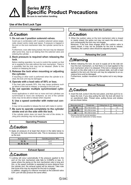
1. Insert the bolt, screw it into the lock piston, and then pull it to release<br />
the lock. If you stop pulling the bolt, the lock will return to<br />
an operational state. Thread sizes, pulling forces and strokes<br />
are as shown below.<br />
Bore size (mm)<br />
12, 16<br />
20, 25, 32<br />
40<br />
Thread size<br />
M2 x 15l or more<br />
M3 x 30l or more<br />
M3 x 30l or more<br />
Pulling force N<br />
2<br />
3<br />
4<br />
∗ Remove the bolt for normal operation.<br />
It can cause lock malfunction or faulty release.<br />
Stroke (mm)<br />
1.5<br />
2<br />
3<br />
Caution<br />
Operating Pressure<br />
1. Apply air pressure of at least that shown in the table below to<br />
the port on the lock mechanism side. This is necessary to release<br />
the lock.<br />
Bore size (mm)<br />
12, 16<br />
20, 25, 32, 40<br />
Operating pressure MPa<br />
0.17<br />
0.15<br />
Caution<br />
Exhaust Speed<br />
1. Locking will occur automatically if the pressure applied to the<br />
port on the lock mechanism side falls to 0.05MPa or less. In<br />
cases where the piping on the lock mechanism side is long and<br />
thin, or the speed controller is separated at some distance from<br />
the cylinder port, the exhaust speed will be reduced. Take note<br />
that some time may be required for the lock to engage.<br />
In addition, clogging of a silencer mounted on the solenoid valve<br />
EXH. port will also produce the same effect.<br />
3-50