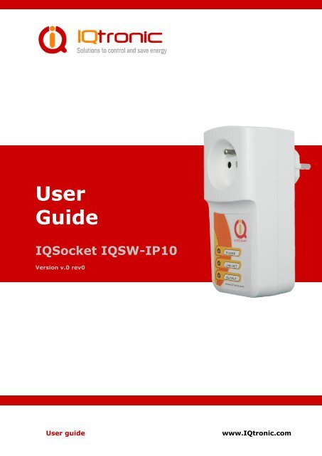
User Guide IQSocket IQSW-IP10
User Guide IQSocket IQSW-IP10
User Guide IQSocket IQSW-IP10

Create successful ePaper yourself
Turn your PDF publications into a flip-book with our unique Google optimized e-Paper software.
<strong>User</strong><br />
<strong>Guide</strong><br />
<strong>IQSocket</strong> <strong>IQSW</strong>-<strong>IP10</strong><br />
Version v.0 rev0<br />
<strong>User</strong> guide<br />
www.IQtronic.com
Important information........................................................................... 3<br />
1 Introduction .................................................................... 4<br />
1.1 Product features ........................................................................... 5<br />
2 Installation ..................................................................... 6<br />
2.1 Wiring the IQsocket <strong>IQSW</strong>-<strong>IP10</strong> ...................................................... 6<br />
2.2 Powering <strong>IQSW</strong>-<strong>IP10</strong> On ................................................................ 7<br />
3 Managing <strong>IQSW</strong>-<strong>IP10</strong> ...................................................... 8<br />
3.1 Setting IP addresses ..................................................................... 8<br />
3.2 Managing by web browser .............................................................. 8<br />
3.2.1 Status page .......................................................................... 9<br />
3.2.2 Network configuration ........................................................... 10<br />
3.2.3 Test rules – watchdog function ............................................... 13<br />
3.2.4 Utility ................................................................................. 17<br />
3.2.5 Control socket...................................................................... 19<br />
3.2.6 Logging ............................................................................... 22<br />
3.2.7 Quick setup ......................................................................... 23<br />
3.2.8 Automatic correction of parameter values ............................... 24<br />
3.3 SNMP ......................................................................................... 25<br />
3.3.1 Example - using SNMP under OS Windows .............................. 26<br />
3.3.2 Example - using SNMP under OS Linux ................................... 28<br />
3.3.3 SNMP trap example .............................................................. 28<br />
3.4 Status data in XML format ............................................................. 29<br />
3.5 IQLocator utility ........................................................................... 29<br />
4 Indicators ..................................................................... 32<br />
5 Output socket wiring diagram ....................................... 33<br />
6 Reset to factory default using push button ................... 33<br />
7 Technical specification .................................................. 34<br />
7.1 Operation, maintenance and safety recommendations ...................... 35<br />
8 Ordering and accessories .............................................. 36<br />
<strong>User</strong> guide<br />
www.IQtronic.com
©2011 IQtronic, Ltd<br />
Important information<br />
Every effort has been taken to ensure the accuracy of this document, however<br />
we do not accept responsibility for damage, injury, loss or expense resulting<br />
from errors and omissions, and we reserve the right of amendment without<br />
further notice.<br />
WARNING: This product is not designed for use in, and should not be used for,<br />
medical applications.<br />
The product doesn’t guarantee safe power source disconnection, only functional<br />
switching of power is performed.<br />
The product contains no serviceable parts, or internal adjustments. No attempt<br />
must be made to repair this product. Faulty units must be returned to supplier<br />
for repair. Improper use, disassembling or product modification causes<br />
warranty loss.<br />
Page 3 of 36
©2011 IQtronic, Ltd<br />
1 Introduction<br />
IQsocket <strong>IQSW</strong>-<strong>IP10</strong> is a member of family of intelligent power sockets brought<br />
to you by IQtronic, Ltd.<br />
IQsocket <strong>IQSW</strong>-<strong>IP10</strong> allows you to control of any electric appliance connected<br />
to the device’s socket remotely over any IP network, including internet. You can<br />
use for this purpose any device supporting internet browser (HTTP protocol)<br />
such as PC, smartphone etc) or using SNMP protocol.<br />
Output power socket: Connect your<br />
electric appliance here. This socket is<br />
intelligent, can be controlled remotely,<br />
manually or automatically (scheduler).<br />
Power plug: Input of AC power for<br />
product and also for connected<br />
appliance. Fits into electric<br />
socket/outlet.<br />
LED indicators: Inform you about<br />
device status.<br />
RJ-45 socket: Connect it into your<br />
Ethernet network<br />
Push button: For turning on/ off<br />
power socket manually or resetting<br />
configuration to factory default values.<br />
Besides controlling of the socket via IP protocol, IQsocket <strong>IQSW</strong>-<strong>IP10</strong> is<br />
equipped with a choice of useful functions, including:<br />
Push button for manual control of the socket<br />
Watch dog function based on evaluation of ICMP packet loss<br />
Time scheduler function, allowing switching on/off your appliance based on<br />
day of week and time.<br />
Page 4 of 36
©2011 IQtronic, Ltd<br />
1.1 Product features<br />
In general, IQsocket <strong>IQSW</strong>-<strong>IP10</strong> has following features:<br />
Controlling (turn on, turn off; restart by cutting power for short time)<br />
of any electric appliance connected to the switched socket by HTTP and<br />
SNMP protocols or manually by pressing pushbutton on <strong>IQSW</strong>-<strong>IP10</strong><br />
body<br />
Configuring <strong>IQSW</strong>-<strong>IP10</strong> parameters by HTTP or SNMP protocols,<br />
password protected<br />
XML and HTML status page, can be excluded from password protection,<br />
for easier integration with your web applications<br />
Can send SNMP traps<br />
IQLocator configuration utility allowing to autodiscovery your IQsocket<br />
devices within LAN network, setup IP address and upgrade firmware<br />
Automatic control based on evaluation of ICMP packet loss with up to<br />
three independent rules – watchdog function<br />
Automatic control based on day of week and time – scheduler function<br />
Real time clock synchronized using NTP protocol<br />
On board temperature sensor to monitor internal temperature<br />
Support remote firmware upgrade<br />
Event log storing up to last 50 events, such as socket on/off changes,<br />
device startups, LAN port connectivity, firmware upgrade etc.<br />
Tiny footprint firmware is efficiently coded in C/assembler, there is no<br />
Linux or other operating system inside, so startup times are really<br />
short (
©2011 IQtronic, Ltd<br />
2 Installation<br />
Before starting installation, please read this manual and take into account<br />
Important information section at beginning of this manual.<br />
2.1 Wiring the IQsocket <strong>IQSW</strong>-<strong>IP10</strong><br />
Wiring is intuitive, simply wire RJ-45 jack into your Ethernet network using<br />
supplied cable, then connect your electric appliance to the device’s socket and<br />
plug the <strong>IQSW</strong>-<strong>IP10</strong> into a free electric socket.<br />
Controlled power socket: Connect<br />
your electric appliance here.<br />
Power plug: Plug the <strong>IQSW</strong>-<strong>IP10</strong> into<br />
an electrical socket.<br />
RJ-45 socket: For connecting <strong>IQSW</strong>-<br />
<strong>IP10</strong> with your Ethernet network.<br />
Note…<br />
Both the socket and the plug of the <strong>IQSW</strong>-<strong>IP10</strong> follow the same<br />
international standard and nominal voltage rating. Ensure you<br />
ordered proper international version of the <strong>IQSW</strong>-<strong>IP10</strong> suitable<br />
for your country<br />
WARNING!<br />
Please respect maximum current rating of switched socket -<br />
16A for resistive load. Do not overload your <strong>IQSW</strong>-<strong>IP10</strong>, as this<br />
may damage or shorten life span of the internal switching<br />
relay, which is not covered by warranty. It is recommended to<br />
use external contactor in case of higher current is required<br />
and/or capacitive/inductive load will be used.<br />
Page 6 of 36
©2011 IQtronic, Ltd<br />
2.2 Powering <strong>IQSW</strong>-<strong>IP10</strong> On<br />
Once you plug your IQsocket <strong>IQSW</strong>-<strong>IP10</strong> into a live electric socket, it become<br />
powered on and starts operation.<br />
You can verify it by observing status of the LEDs:<br />
Once AC power is connected, all three LED indicators will blink shortly<br />
and internal self-test is performed. Then, if everything is ok, the Power<br />
LED (Red) will blink every second.<br />
LINK/ACT (Green) – solid light indicated established Ethernet link,<br />
blanked for short time when an Ethernet activity occurs<br />
The Output LED (Yellow) indicates state of output socket. Sold light<br />
means socket is active – appliance plugged into the output socket is<br />
operating and vice versa.<br />
Please see chapter 3.5 for more information on LED indicators.<br />
Your <strong>IQSW</strong>-<strong>IP10</strong> is now ready for use.<br />
Page 7 of 36
©2011 IQtronic, Ltd<br />
3 Managing <strong>IQSW</strong>-<strong>IP10</strong><br />
This chapter guides you through management and configuration of <strong>IQSW</strong>-<strong>IP10</strong>.<br />
Your IQsocket <strong>IQSW</strong>-<strong>IP10</strong> is equipped with an internal web server, which<br />
provides an easy to use, intuitive and convenient way of management. You can<br />
both set up configuration and operation parameters and get information about<br />
device’s status. There is also support for SNMP protocol, allowing to integrate<br />
your <strong>IQSW</strong>-<strong>IP10</strong> into any SNMP management suite.<br />
In order to access the web interface, it is necessary to setup IP network<br />
address on your PC properly.<br />
3.1 Setting IP addresses<br />
Default IP address of the IQsocket <strong>IQSW</strong>-<strong>IP10</strong> is 192.168.0.100, network mask<br />
255.255.255.0.<br />
In order to access your <strong>IQSW</strong>-<strong>IP10</strong>, it is necessary to setup IP address of your<br />
computer, connected to the same Ethernet network as the <strong>IQSW</strong>-<strong>IP10</strong> properly<br />
– in this case set the IP address of the network adapter to 192.168.11, mask<br />
255.255.255.0.<br />
You can also change the IP address of your <strong>IQSW</strong>-<strong>IP10</strong> using IQLocator utility,<br />
see chapter 3.5 for more information.<br />
3.2 Managing by web browser<br />
Once you have properly set IP address of your PC, open the address of your<br />
<strong>IQSW</strong>-<strong>IP10</strong> (default 192.168.0.100) in your favorite internet browser:<br />
If everything is ok, status page will be displayed.<br />
Page 8 of 36
©2011 IQtronic, Ltd<br />
3.2.1 Status page<br />
Provides summary of device status:<br />
Explanation of parameters:<br />
Section System information provide basic status information, such as Device<br />
name and Location, info on time, firmware version, Ethernet MAC address and<br />
temperature reading of internal temperature sensor.<br />
Section Last event provides date/time of last change of socket state and<br />
current socket state.<br />
Section Rules status informs about currently active automatic rules evaluating<br />
ICMP packet loss to chosen hosts.<br />
Page 9 of 36
©2011 IQtronic, Ltd<br />
3.2.2 Network configuration<br />
Here you can configure networking and security parameters:<br />
Page 10 of 36
©2011 IQtronic, Ltd<br />
Explanation of parameters:<br />
IP address<br />
You can setup IP networking parameters such as IP address, Network mask<br />
Default Gateway, DNS servers; please ensure to enter proper values. Please<br />
note it is necessary to define a fixed IP address even if case you are using a<br />
DHCP environment.<br />
Note…<br />
When your local network is using private addresses behind<br />
a NAT router and you would like to make your <strong>IQSW</strong>-<strong>IP10</strong><br />
accessible from the Internet, it is necessary to setup port<br />
mapping (forwarding, server rule) in your router for the IP<br />
address assigned to <strong>IQSW</strong>-<strong>IP10</strong> and selected ports, e.g.<br />
port TCP 80 for accessing web interface.<br />
SOHO example: Your network contains a modem/router with NAT for internet<br />
access, having IP address 192.168.1.254. Simply find an unused IP address<br />
from the private network range it use (192.168.1.1-192.168.1.253) e.g.<br />
192.168.1.200, double check it is not used e.g. by using Ping command from<br />
your PC:<br />
C:\>ping 192.168.1.200<br />
Pinging 192.168.1.200 with 32 bytes of data:<br />
Request timed out.<br />
Then assign the 192.168.1.200 to the <strong>IQSW</strong>-<strong>IP10</strong> by either IQLocator utility or<br />
by web interface and use address of the router (192.168.1.254) in both<br />
Gateway and DNS fields.<br />
NTP setup<br />
<strong>IQSW</strong>-<strong>IP10</strong> can synchronize its clock from an NTP (Network Time Protocol)<br />
server, please don’t forget also to define time zone. Please note NTP feature<br />
will work only if <strong>IQSW</strong>-<strong>IP10</strong> will have access to the Internet.<br />
Note…<br />
It is highly recommended define NTP properly and allow<br />
your <strong>IQSW</strong>-<strong>IP10</strong> accessing the Internet; otherwise logging<br />
and scheduler feature can’t work properly.<br />
Page 11 of 36
©2011 IQtronic, Ltd<br />
Password protection<br />
You can change/define a login username and password for protecting access to<br />
web interface. It comes with no password by default.<br />
Note…<br />
If you want to disable password protection, enter blank<br />
login password.<br />
You can also activate exception from password protection for pages status.xml<br />
and/or status/html – when exceptions are active, those pages will be then<br />
always available without password, which is useful for further processing of the<br />
status information e.g. by scripts.<br />
HTTP port<br />
It is possible to change port for the web interface from default value 80 by<br />
entering new value to HTTP port field.<br />
SNMP<br />
SNMP can be deactivated by unchecking the SNMP checkbox, it is active by<br />
default. You can change passwords for SNMP read and write communities<br />
(default value is “public”). When there is an output control event resulting from<br />
assessment of automatic packet loss rules – the watchdog feature; <strong>IQSW</strong>-<strong>IP10</strong><br />
can send SNMP trap messages to defined IP address besides operating the<br />
relay of the socket, simply check particular check boxes Relay and/or Send<br />
TRAP.<br />
The SNMP time for restart defines how long is socket turned off when restart<br />
command is issued via SNMP.<br />
Add log events<br />
You can select, which events to write into the event log: Power UP will write<br />
event at every device startup and time has been successfully synchronized<br />
from NTP server; Ethernet LINK will write event at every time when Ethernet<br />
link has been established.<br />
Output socket state after startup<br />
You can choice which state will have output socket after device will be powered<br />
on: to be off, on, or to remember last state before device has been turned<br />
off/power has been lost.<br />
Page 12 of 36
©2011 IQtronic, Ltd<br />
3.2.3 Test rules – watchdog function<br />
You can configure here automatic watch dog function based on assessment of<br />
ICMP packet lost to selected IP host:<br />
Basically, you can define up to three test rules, two with numerical IP address<br />
of evaluated host, third rule can be defined using host name, and it’s IP<br />
address will be resolved via DNS. Each rule is sending periodically ICMP test<br />
packets to the host and when number of received ICMP replies is lower than<br />
allowed packet loss, rule will generate request for output control event, which<br />
Page 13 of 36
©2011 IQtronic, Ltd<br />
can lead to restart of the output socket, sending of SNMP trap or both,<br />
depending on configuration. Finally, output control event is performed using<br />
logical OR or logical AND operations over the results (output control event<br />
requests) of particular rules.<br />
Defining rules<br />
Each rule can be enabled or disabled by checking the checkbox. Enter IP<br />
address (Rule 1, Rule 2) or host name in case of the Rule 3, then size of ICMP<br />
frames, maximum allowed packet loss in % and Packet timeout interval, time<br />
how long will device wait for answers from the host – ICMP answers coming<br />
later that the Packet timeout will be considered as lost.<br />
Note…<br />
If you set Packet timeout to 0 (zero) value, device will use<br />
the value of Interval for send test packet as the Packet<br />
timeout interval.<br />
Rules evaluation<br />
You can define periodicity of sending test ICMP packets by entering it into<br />
Interval for send test packet field with allowed range 2-20 seconds.<br />
Interval for next test is time delay till testing will begin after device has been<br />
started up or a rule has been activated (packet loss to a host detected).<br />
You can limit maximum number of consecutive restart attempts by setting<br />
Maximum consecutive restarts parameter to prevent continuous restarting e.g.<br />
if there is a serious problem preventing target host to be recovered back by a<br />
restart via power cycling.<br />
Restart socket hold time determines time interval how long is cut power of the<br />
output socket during a restart attempt.<br />
Page 14 of 36
©2011 IQtronic, Ltd<br />
Number of packets to evaluate represents how many test packets is used for<br />
evaluation of packet loss.<br />
Rules evaluation allows to choose when an output control event (restart and/or<br />
SNMP trap) will be performed – in case of selected OR, it will be performed<br />
when ANY from rules is positive; while AND require that ALL rules must be<br />
positive.<br />
Page 15 of 36
©2011 IQtronic, Ltd<br />
Diagram of rules evaluation<br />
All referenced values come from Test rules settings page. Request means<br />
testing ICMP packets sent to the target host; response means received ICMP<br />
answers from the target host.<br />
Page 16 of 36
©2011 IQtronic, Ltd<br />
3.2.4 Utility<br />
This page gives you possibility to restore factory default configuration, reboot<br />
device, upgrade firmware and clear statistics data:<br />
Restoring default configuration<br />
Restore default configuration will revert all settings to the factory default<br />
values. It is necessary to reboot the device in order to activate new values<br />
using Reboot button:<br />
Page 17 of 36
©2011 IQtronic, Ltd<br />
Clearing statistics<br />
Clear statistic data will erase all collected statistics data displayed in Status<br />
page.<br />
Firmware upgrade<br />
Using Browse button select file containing new firmware and then click to<br />
Upload. Upgrade process will take about 50 seconds, which is indicated by fast<br />
blinking of the Power LED (red) and following message will be displayed I case<br />
of success:<br />
In case of an error will be detected, following message will be displayed:<br />
Note…<br />
You can also upgrade firmware using IQLocator utility,<br />
please see chapter 3.5 for more information.<br />
WARNING!<br />
Do not remove power during a firmware upgrade process, as it<br />
can render your device inoperational!<br />
Page 18 of 36
©2011 IQtronic, Ltd<br />
3.2.5 Control socket<br />
Here you can control the output socket manually and schedule automatic<br />
actions based on date/time.<br />
Page 19 of 36
©2011 IQtronic, Ltd<br />
Socket status<br />
Top of the page contains status row displaying current status of the socket:<br />
Manual control<br />
Simply click to the buttons to turn on, turn off and restart (change current<br />
state to opposite one temporary for given number of seconds).<br />
Scheduler<br />
This feature allows you to schedule output socket status, up to 50 records are<br />
supported.<br />
Scheduler function use date/time synchronized by NTP protocol, so your <strong>IQSW</strong>-<br />
<strong>IP10</strong> must have access to the Internet (or to an NTP server located within your<br />
private network), see also chapter 3.2.2.<br />
Each scheduler record defines target socket state at given time. It is allowed to<br />
manually control the socket while scheduler is active – each change is done<br />
only at particular time.<br />
Each scheduler record is having following structure:<br />
DOW,…DOW,HH:MM, action<br />
Where:<br />
o DOW means Day of week, coded as first two letters of English day<br />
names: Mo, Tu, We, Th, Fr, Sa, Su;<br />
o HH:MM means time in form of hour:minute in 24h format;<br />
o Action means target socket state – off, on.<br />
Example<br />
Page 20 of 36
©2011 IQtronic, Ltd<br />
Enter following rows:<br />
Mo,Tu,We,Th,Fr,Sa,Su,20:00,Off by clicking to Save button<br />
Mo,Tu,We,Th,Fr,Sa,Su,21:00,On by clicking to Save button<br />
and then activate scheduler by clicking to checkbox Enable scheduler<br />
So scheduler will every day at 20:00 turn the output socket off and turn it on<br />
daily at 21:00.<br />
You can use any combination of days of week, such as:<br />
Sa,Su, 20:00, Off<br />
Sa,Su, 21:00, On<br />
to control the socket during weekends.<br />
I you want to delete particular scheduler row, simply enter copy of the row and<br />
click to Delete button; you can also enter a part of row and all similar rows will<br />
be deleted.<br />
If you want to delete all scheduler records, enter text ALL and click to Delete<br />
button.<br />
Page 21 of 36
©2011 IQtronic, Ltd<br />
3.2.6 Logging<br />
This page display events recorded in the event log:<br />
Event log can contain up to 50 records, oldest records being rewritten when<br />
log is full.<br />
Automatically are recorded socket change events and firmware upgrade,<br />
optionally Ethernet link status and device startups, which can be configured in<br />
Network configuration menu.<br />
All events are time stamped when time has been successfully obtained from an<br />
NTP server, so your <strong>IQSW</strong>-<strong>IP10</strong> must have access to the Internet (or to an NTP<br />
server located within your private network), see also chapter 3.2.2.<br />
Events can be sorted by time, ascending or descending, or normal by recorded<br />
order, you can choice sorting by clicking to the sort button.<br />
Explanation of event types<br />
Upgraded new firmware<br />
an upgrade firmware has been done<br />
POWER UP 0<br />
POWER UP 1<br />
device has been turned on by applying<br />
power<br />
device has been manually rebooted<br />
Page 22 of 36
©2011 IQtronic, Ltd<br />
Restart www.domain.com 100%<br />
DEVICE OVERHEAT<br />
TURN ON by BUTTON<br />
TURN OFF by BUTTON<br />
TURN ON by SCHED<br />
TURN OFF by SCHED<br />
restart due to www.domain.com has been<br />
inaccessible, with ICMP packet loss 100%<br />
Overheat condition, allowed internal<br />
temperature is 50°C.<br />
socket has been turned on by the push<br />
button<br />
socket has been turned off by the push<br />
button<br />
socket has been turned on by scheduler<br />
socket has been turned off by scheduler<br />
3.2.7 Quick setup<br />
This page provides setting up of basic networking and ICMP packet loss test<br />
rule parameters of <strong>IQSW</strong>-<strong>IP10</strong> in an easy way suitable to less experienced<br />
users.<br />
Page 23 of 36
©2011 IQtronic, Ltd<br />
In case of settings entered are wrong or missing, user is informed about it the<br />
status row; settins then must be repeated until they are accepted, which is<br />
indicated by following messgae in the status row:<br />
New settings is then passed into Test rules and are activated.<br />
Possible errors include:<br />
An IP address of destination host out of current IP network range has been<br />
entered, but Gateway setting is missing or it is wrong.<br />
Destination host IP address is missing.<br />
Gateway setting is missing, it is always required for a host specified by domain<br />
name.<br />
If target host is specified by domain name, it is necessary to define also a DNS<br />
server which will be used to resolve IP address of the host.<br />
3.2.8 Automatic correction of parameter values<br />
WEB configuration interface has implemented function to detect incorrect<br />
parameter range. In such an attempt to enter a wrong value, an error<br />
message will be displayed in status row, the original value of parameter will be<br />
reverted back and displayed with red background:<br />
Page 24 of 36
©2011 IQtronic, Ltd<br />
3.3 SNMP<br />
IQsocket <strong>IQSW</strong>-<strong>IP10</strong> contains support for SNMPv1.0 protocol, which makes<br />
possible to integrate it into any SNMP management suite. Advantage is also<br />
very small volume of data trafic required for SNMP. You can both monitor<br />
status and statistics using the GET commands and control output socket by<br />
using the SET command.<br />
SNMP MIB table:<br />
SNMP MIB table can be displayed at any time via WEB configuration interface<br />
by clicking to „For MIB INFO click here, please“ link in Network configuration<br />
page (see chapter 3.2.2, where you can enable/disable SNMP, setup SNMPrelated<br />
settings such as SNMP read/write communities, the trap address and<br />
Page 25 of 36
©2011 IQtronic, Ltd<br />
also configuring output control event behavior of the automatic packet-loss<br />
evaluating watch dog function to either control output socked, and/or sending<br />
SNMP trap. SNMP feature is enabled by default.<br />
3.3.1 Example - using SNMP under OS Windows<br />
There is plenty of SNMP utilities available under Windows OS, for example<br />
iReasoning MIB browser (www.ireasoning.com) or PRTG Network Monitor<br />
(www.paesler.com).<br />
After installation of software, let’s run it and configure it to work with IQsocket<br />
<strong>IQSW</strong>-<strong>IP10</strong>:<br />
Enter IP address of the <strong>IQSW</strong>-<strong>IP10</strong> (default value 192.168.0.100) and click to<br />
Advanced:<br />
Here we will set Read and Write communities, matching settings of the <strong>IQSW</strong>-<br />
<strong>IP10</strong> (defaut values are „public“). Then we can read from device value of each<br />
settings from the MIB table:<br />
Page 26 of 36
©2011 IQtronic, Ltd<br />
In order to control the output socket of the <strong>IQSW</strong>-<strong>IP10</strong>, use menu SET:<br />
Value 0 means turn off; 1 means turn on.<br />
After successful command execution, a confirmation message will be<br />
displayed:<br />
Page 27 of 36
©2011 IQtronic, Ltd<br />
3.3.2 Example - using SNMP under OS Linux<br />
Thanks to extensive support of SNMP in Linux OS, we can directly use<br />
commands snmpget and snmpset:<br />
Obtaining status of the output socket: (<strong>IQSW</strong>-<strong>IP10</strong> is on IP 192.168.2.54 in<br />
this example:<br />
Returned value 1 means socket is turned on; 0 means turned off.<br />
To control status of the output socket: (<strong>IQSW</strong>-<strong>IP10</strong> is on IP 192.168.2.54 in<br />
this example:<br />
In this example, we restarted appliance connected to the output socket –<br />
power has been cut for time defined in Network configuration page.<br />
3.3.3 SNMP trap example<br />
In order to test SNMP traps, you can use TRAP receiver integrated in the<br />
iReasoning MIB browser.<br />
Page 28 of 36
©2011 IQtronic, Ltd<br />
3.4 Status data in XML format<br />
IQsocket <strong>IQSW</strong>-<strong>IP10</strong> contains status page in XML format, it can be accessed at<br />
/status.xml.<br />
You can select if this page will be protected by password on not by setting<br />
exceptions at Network configuration page, see chapter 3.2.2.<br />
The status.xml page use following format:<br />
<br />
IP SOCKET <br />
Location<br />
0days 0hrs 2mins <br />
0days 0hrs 2mins <br />
1.0.0<br />
00:19:51:10:05:29<br />
27.1<br />
0days 0hrs 2mins <br />
Turned ON<br />
0<br />
<br />
<br />
<br />
<br />
<br />
<br />
<br />
<br />
<br />
<br />
<br />
<br />
<br />
<br />
<br />
<br />
<br />
<br />
<br />
<br />
<br />
<br />
<br />
<br />
<br />
3.5 IQLocator utility<br />
Purpose of IQLocator.exe utility is to make easier and faster initial<br />
configuration by locating your <strong>IQSW</strong>-<strong>IP10</strong> using autodiscover, to change IP<br />
address and upgrade device firmware.<br />
Page 29 of 36
©2011 IQtronic, Ltd<br />
Simply connect your <strong>IQSW</strong>-<strong>IP10</strong> with your computer or local Ethernet network<br />
using supplied cable and run the IQLocator.exe. After clicking to Scan button, a<br />
list of found devices will be displayed:<br />
In order to change device IP address, select particular device by clicking to the<br />
row and then click to button “SET IP addresses” button:<br />
Once you enter new IP address and click to “Set”<br />
button, a confirmation message “IP address was<br />
successfully set” will be displayed and new SCAN<br />
process will be performed to locate your device<br />
with new IP address. This IP address setting is<br />
temporary, valid until next device start. To make<br />
change IP permanent, it is necessary to use WEB<br />
management (see chapter 3.2.2) to save changes<br />
permanently.<br />
You can upgrade firmware similar way by clicking to “Upload firmware” button.<br />
Page 30 of 36
©2011 IQtronic, Ltd<br />
After browsing the target file containing<br />
new firmware and clicking to “Upload”<br />
button, a progress bar will be displayed.<br />
Green Link LED indicator will blink during<br />
upload process.<br />
When upload is finished, a confirmation message “Successful” will appear and<br />
now it is necessary to wait about 30seconds till internal firmware rewrite<br />
procedure finishes, during which the Power LED (red) will blinking fast. Then<br />
an automatic reboot of device will be performed and device is ready for use<br />
now.<br />
WARNING!<br />
Do not remove power during a firmware upgrade process, as it<br />
can render your device inoperational!<br />
Page 31 of 36
©2011 IQtronic, Ltd<br />
4 Indicators<br />
The IQsocket <strong>IQSW</strong>-<strong>IP10</strong> is equipped with three LED indicators:<br />
POWER<br />
BLINKS RED 1x PER SECOND<br />
BLINKS RED FAST<br />
LINK/ACT<br />
LIGHTS GREEN<br />
BLINKING<br />
OUTPUT<br />
NOT ACTIVE<br />
LIGHTS YELLOW<br />
Input power and operation OK<br />
Firmware upgrade in progress, do not remove power!<br />
Link to Ethernet network established<br />
Ethernet activity in progress<br />
Output socket is OFF<br />
Output socket is ON<br />
Page 32 of 36
©2011 IQtronic, Ltd<br />
5 Output socket wiring diagram<br />
Device uses a single pole relay switch, so it is not<br />
performing safe power disconnection of the<br />
appliance plugged into socket, only functional<br />
switching is performed.<br />
6 Reset to factory default using push button<br />
Each device come from factory preconfigured with factory default values.<br />
Device can be anytime returned back to these default values by using reset to<br />
factory defaults procedure.<br />
Besides using web management, reset can be also done by the push button<br />
located near to the RJ-45 socket.<br />
In order to restore factory default configuration, push the button for at least 5<br />
seconds and then release. All LED indicators should start blinking for next 10<br />
seconds. Please press the button again within these 10 seconds to confirm<br />
reset to factory default procedure. After this step is your device in original<br />
factory configuration.<br />
WARNING!<br />
Please BE CAREFULL! This step will erase all settings of your<br />
IQsocket <strong>IQSW</strong>-<strong>IP10</strong>.<br />
Page 33 of 36
©2011 IQtronic, Ltd<br />
7 Technical specification<br />
Model<br />
Mains power<br />
IQsocket <strong>IQSW</strong>-<strong>IP10</strong>-E, CEE 7/5 French type socket<br />
IQsocket <strong>IQSW</strong>-<strong>IP10</strong>-F, CEE 7/4 "Schuko” earthed<br />
IQsocket <strong>IQSW</strong>-<strong>IP10</strong>-N, NEMA 5-15 USA socket<br />
IQsocket <strong>IQSW</strong>-<strong>IP10</strong>-B British BS 1363<br />
100-230VAC / 50-60Hz,<br />
own consumption 3Watts<br />
Output socket load<br />
Management<br />
Security<br />
Indicators<br />
Features<br />
Dimensions<br />
Weight<br />
16A max (resistance load)<br />
HTTP web management interface<br />
SNMPv1.0<br />
Manual control using push button<br />
Password for logging into web management interface<br />
SNMP read/write community passwords<br />
POWER: red LED<br />
Link: green LED<br />
RELAY: yellow LED<br />
Appliance control over any TCPIP networky<br />
Remote restart of appliances<br />
Automatic watchdog based on ICMP packet loss monitoring<br />
Scheduler<br />
(LxWxH) 140 x 65 x 55mm(92mm w/ plug)<br />
0.2kg netto<br />
Operating temperature 0 to +50 ˚C<br />
Humidity<br />
Max. 80%, non-condensing<br />
Environment protection IP40, for normal environment<br />
Installation category Class II, overvoltage max. 2500V<br />
Compliance<br />
CE, FCC<br />
Page 34 of 36
©2011 IQtronic, Ltd<br />
7.1 Operation, maintenance and safety recommendations<br />
Do not modify product in any way and do not operate product modified<br />
any way. Warranty is void when product was disassembled or modified<br />
in any way.<br />
Product is not fused; ensure it is installed in fused electric installation<br />
only.<br />
Product can be operated only indoor office/house environment. Do not<br />
expose it to humid, wet nor chemically aggressive environment.<br />
Product is not designed for industrial operation with aggressive<br />
environment.<br />
Don’t expose product to vibrations, shaking or fall downs to avoid<br />
product damage.<br />
Load current 16A is valid for resistive load. If you need to switch an<br />
non-resistive or higher current load, use an external contactor rated<br />
for target load among the product. Switching a non-resistive load or<br />
higher than nominal rating currents can cause permanent damage of<br />
switching elements, which is not covered by warranty.<br />
WARNING: This product is not designed for use in, and should not be<br />
used for, medical applications.<br />
Page 35 of 36
©2011 IQtronic, Ltd<br />
8 Ordering and accessories<br />
IQsocket product family uses following ordering code system:<br />
IQSx-y-z<br />
Example: <strong>IQSW</strong>-<strong>IP10</strong>-F<br />
Product family: W=WALL | R=RACK | D=DIN | B=Board<br />
Product model: GSM | GSML | GSMRF | IP | RS232 | HDO | IPGSM<br />
Electric standard of plug/socket: F=Schuko | E=French, B=British, N=USA<br />
Ordering code<br />
Code<br />
<strong>IQSW</strong>-<strong>IP10</strong>-X<br />
Description<br />
pls specify socket type in place of X<br />
Page 36 of 36