- Page 1 and 2:
Garney Construction 785 E Warren Ga
- Page 3 and 4:
PROJECT SUBMITTAL Project Owner: Wa
- Page 5 and 6:
Tab 3. Product References Circuit
- Page 7 and 8:
Practices that Guard against ESD Th
- Page 9 and 10:
Handling Sensitive Components Corre
- Page 11 and 12:
What Causes Electrostatic Damage? E
- Page 13:
If we pick up the chip, it becomes
- Page 16 and 17:
Safety Guidelines for the Applicati
- Page 18 and 19:
Section 1: Definitions 3 Section 1:
- Page 20 and 21:
Section 2: General Authorized Engin
- Page 22 and 23:
Section 2: General Authorized Engin
- Page 24 and 25:
Section 3: Application Guidelines 9
- Page 26 and 27:
Section 3: Application Guidelines 1
- Page 28 and 29:
Section 3: Application Guidelines 1
- Page 30 and 31:
Section 3: Application Guidelines 1
- Page 32 and 33:
Section 3: Application Guidelines 1
- Page 34 and 35:
Section 4: Installation Guidelines
- Page 36 and 37:
Section 4: Installation Guidelines
- Page 38 and 39:
Section 5 : Preventive Maintenance
- Page 40 and 41:
Section 5 : Preventive Maintenance
- Page 43 and 44:
Publication SGI - 1.1 — January 2
- Page 45 and 46:
Important User Information Solid-st
- Page 47 and 48:
soc-ii Summary of Changes Notes: Pu
- Page 49 and 50:
ii Table of Contents Chapter 6 Appe
- Page 51 and 52:
P-2 Overview Recommended Cable/Wire
- Page 53 and 54:
1-2 Wire/Cable Types General Materi
- Page 55 and 56:
1-4 Wire/Cable Types Figure 1.3 Cab
- Page 57 and 58:
1-6 Wire/Cable Types Type 3 Install
- Page 59 and 60: 1-8 Wire/Cable Types Type 3 Install
- Page 61 and 62: 1-10 Wire/Cable Types Input Power C
- Page 63 and 64: 1-12 Wire/Cable Types Analog Signal
- Page 65 and 66: 1-14 Wire/Cable Types Remote I/O an
- Page 67 and 68: 2-2 Power Distribution Delta/Delta
- Page 69 and 70: 2-4 Power Distribution TN-S Five-Wi
- Page 71 and 72: 2-6 Power Distribution Transformer
- Page 73 and 74: 2-8 Power Distribution Table 2.C AC
- Page 75 and 76: 2-10 Power Distribution Drive Catal
- Page 77 and 78: 2-12 Power Distribution PowerFlex 7
- Page 79 and 80: 2-14 Power Distribution 1336 Family
- Page 81 and 82: 2-16 Power Distribution Example: Th
- Page 83 and 84: 2-18 Power Distribution Using Power
- Page 85 and 86: 2-20 Power Distribution Braking Cho
- Page 87 and 88: 3-2 Grounding Grounding PE or Groun
- Page 89 and 90: 3-4 Grounding The grounding scheme
- Page 91 and 92: 3-6 Grounding Effective Grounding P
- Page 93 and 94: 3-8 Grounding Notes: Publication DR
- Page 95 and 96: 4-2 Practices Zinc-plated steel is
- Page 97 and 98: 4-4 Practices Figure 4.3 Bolt Mount
- Page 99 and 100: 4-6 Practices Figure 4.5 Terminatin
- Page 101 and 102: 4-8 Practices Do not lay one ground
- Page 103 and 104: 4-10 Practices Spacing Notes: 1. Bo
- Page 105 and 106: 4-12 Practices Common Mode Current
- Page 107 and 108: 4-14 Practices Cable Trays When lay
- Page 109: 4-16 Practices Figure 4.14 Plain Co
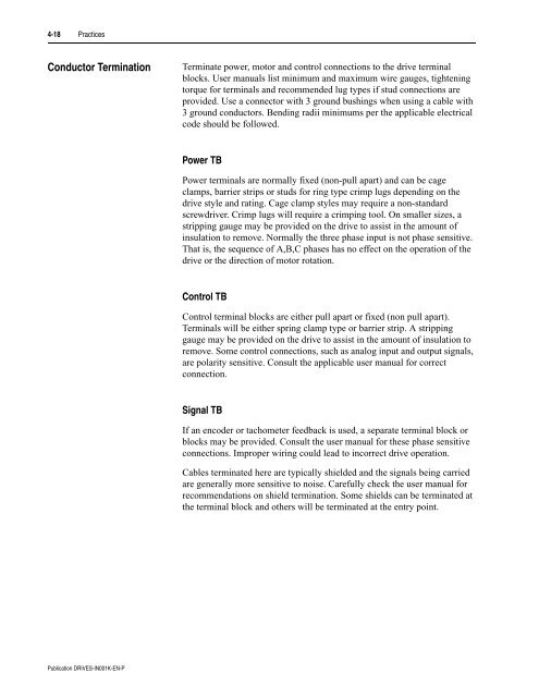
- Page 113 and 114: 4-20 Practices Notes: Publication D
- Page 115 and 116: 5-2 Reflected Wave (CIV) for the ai
- Page 117 and 118: 6-2 Electromagnetic Interference Co
- Page 119 and 120: 6-4 Electromagnetic Interference Pu
- Page 121 and 122: 6-6 Electromagnetic Interference En
- Page 123 and 124: A-2 Motor Cable Length Restrictions
- Page 125 and 126: A-4 Motor Cable Length Restrictions
- Page 127 and 128: A-6 Motor Cable Length Restrictions
- Page 129 and 130: A-8 Motor Cable Length Restrictions
- Page 131 and 132: A-10 Motor Cable Length Restriction
- Page 133 and 134: A-12 Motor Cable Length Restriction
- Page 135 and 136: A-14 Motor Cable Length Restriction
- Page 137 and 138: A-16 Motor Cable Length Restriction
- Page 139 and 140: A-18 Motor Cable Length Restriction
- Page 141 and 142: A-20 Motor Cable Length Restriction
- Page 143 and 144: A-22 Motor Cable Length Restriction
- Page 145 and 146: A-24 Motor Cable Length Restriction
- Page 147 and 148: A-26 Motor Cable Length Restriction
- Page 149 and 150: A-28 Motor Cable Length Restriction
- Page 151 and 152: A-30 Motor Cable Length Restriction
- Page 153 and 154: A-32 Motor Cable Length Restriction
- Page 155 and 156: Glossary-2 Dry Dry locations per Pe
- Page 157 and 158: Glossary-4 Notes: Publication DRIVE
- Page 159 and 160: Index-2 Ungrounded Secondary, 2-3 D
- Page 161:
Index-4 Surge Protection MOV, 2-17
- Page 173 and 174:
Product Details and Certifications
- Page 175 and 176:
http://raise.rockwellautomation.com
- Page 177 and 178:
Product Details and Certifications
- Page 179 and 180:
Yokogawa Corp. of America - Meter &
- Page 183 and 184:
Career │ Site Map │ Contact Us
- Page 185 and 186:
AMP-TRAP 2000 ® ATQR TIME DELAY/CL
- Page 187 and 188:
AMP-TRAP 2000 ® TIME DELAY/CLASS C
- Page 189 and 190:
Bussmann ® LOW-PEAK ® Time-Delay
- Page 191 and 192:
Bussmann ® LOW-PEAK ® Time-Delay
- Page 194 and 195:
Product Details and Certifications
- Page 196 and 197:
Directory: Tools & Resources|Locati
- Page 198 and 199:
Directory: Tools & Resources|Locati
- Page 200 and 201:
Product Details and Certifications
- Page 202 and 203:
Product Details and Certifications
- Page 204 and 205:
Product Details and Certifications
- Page 206 and 207:
Product Details and Certifications
- Page 208 and 209:
9 KEY BENEFITS Unique protect
- Page 210 and 211:
469 SR Motor Protection System 469
- Page 212 and 213:
469 SR Motor Protection System 469
- Page 214 and 215:
469 SR Motor Protection System 469
- Page 216 and 217:
469 SR Motor Protection System 469
- Page 218 and 219:
Product Details Product Details Pro
- Page 220 and 221:
POTENTIAL TRANSFORMERS THREE PHASE
- Page 222 and 223:
PowerFlex 70/700 Production Test Pr
- Page 224 and 225:
PowerFlex 70/700 Production Test Pr
- Page 226 and 227:
TEST PROCEDURE Test No: TEST 5015-0
- Page 228 and 229:
TEST PROCEDURE Test No: TEST 5015-0
- Page 230 and 231:
Customer: The Reynolds Co. End User
- Page 232 and 233:
Harmonic Estimator Report - Summary
- Page 234 and 235:
Harmonic Estimator Report - Spectru
- Page 236 and 237:
Harmonic Estimator Report - Summary
- Page 238 and 239:
Harmonic Estimator Report - Spectru
- Page 240 and 241:
Harmonic Estimator Report - Summary
- Page 242 and 243:
Harmonic Estimator Report - Spectru
- Page 244 and 245:
Harmonic Estimator Report - Summary
- Page 246 and 247:
Harmonic Estimator Report - Spectru
- Page 248 and 249:
Harmonic Estimator Report - Summary
- Page 250 and 251:
Harmonic Estimator Report - Spectru
- Page 252 and 253:
Harmonic Estimator Report - Summary
- Page 254 and 255:
Harmonic Estimator Report - Spectru
- Page 256 and 257:
Harmonic Estimator Report - Summary
- Page 258 and 259:
Harmonic Estimator Report - Spectru
- Page 260 and 261:
Harmonic Estimator Report - Summary
- Page 262 and 263:
Harmonic Estimator Report - Spectru
- Page 264 and 265:
Harmonic Estimator Report - Summary
- Page 266 and 267:
Harmonic Estimator Report - Spectru
- Page 268 and 269:
Harmonic Estimator Report - Summary
- Page 270 and 271:
Harmonic Estimator Report - Spectru
- Page 272 and 273:
Harmonic Estimator Report - Summary
- Page 274 and 275:
Harmonic Estimator Report - Spectru
- Page 276 and 277:
Harmonic Estimator Report - Summary
- Page 278 and 279:
Harmonic Estimator Report - Spectru
- Page 280 and 281:
SMC-Flex Bulletin 150 SMC-Flex Appl
- Page 282 and 283:
Bulletin 150 SMC-Flex Table of Cont
- Page 284 and 285:
Bulletin 150 SMC-Flex Solid-State .
- Page 286 and 287:
Bulletin 150 SMC-Flex Chapter 2 App
- Page 288 and 289:
Bulletin 150 SMC Flex Chapter 1 Int
- Page 290 and 291:
Bulletin 150 SMC Flex Standard Soft
- Page 292 and 293:
Bulletin 150 SMC Flex Figure 1.4: S
- Page 294 and 295:
Bulletin 150 SMC Flex Figure 1.6: C
- Page 296 and 297:
Bulletin 150 SMC Flex Dual Ramp Sta
- Page 298 and 299:
Bulletin 150 SMC Flex Figure 1.10:
- Page 300 and 301:
Bulletin 150 SMC Flex Figure 1.12:
- Page 302 and 303:
Bulletin 150 SMC Flex Preset Slow S
- Page 304 and 305:
Bulletin 150 SMC Flex Figure 1.16:
- Page 306 and 307:
Bulletin 150 SMC Flex Figure 1.18:
- Page 308 and 309:
Bulletin 150 SMC Flex Soft Stop The
- Page 310 and 311:
Bulletin 150 SMC Flex Figure 1.22:
- Page 312 and 313:
Bulletin 150 SMC Flex Figure 1.24:
- Page 314 and 315:
Bulletin 150 SMC Flex Braking Contr
- Page 316 and 317:
Bulletin 150 SMC Flex Figure 1.28:
- Page 318 and 319:
Bulletin 150 SMC Flex Figure 1.30:
- Page 320 and 321:
Bulletin 150 SMC Flex Slow Speed wi
- Page 322 and 323:
Bulletin 150 SMC Flex Figure 1.34:
- Page 324 and 325:
Bulletin 150 SMC Flex Electronic Ov
- Page 326 and 327:
Bulletin 150 SMC Flex The SMC-Flex
- Page 328 and 329:
Bulletin 150 SMC Flex The SMC-Flex
- Page 330 and 331:
Bulletin 150 SMC Flex 2 Overview Ap
- Page 332 and 333:
Bulletin 150 SMC Flex Figure 2.3: P
- Page 334 and 335:
Bulletin 150 SMC Flex Figure 2.5: R
- Page 336 and 337:
Bulletin 150 SMC Flex Figure 2.7: C
- Page 338 and 339:
Bulletin 150 SMC Flex Figure 2.9: O
- Page 340 and 341:
PROTECTIVE MODULE Bulletin 150 SMC
- Page 342 and 343:
Bulletin 150 SMC Flex Built-in Comm
- Page 344 and 345:
Bulletin 150 SMC Flex Multi-motor A
- Page 346 and 347:
Bulletin 150 SMC Flex Part Winding
- Page 348 and 349:
Bulletin 150 SMC Flex SMC-Flex Cont
- Page 350 and 351:
Bulletin 150 SMC Flex SMC-Flex Cont
- Page 352 and 353:
Bulletin 150 SMC Flex Motor Torque
- Page 354 and 355:
Bulletin 150 SMC Flex Chapter 4 Des
- Page 356 and 357:
Bulletin 150 SMC Flex Petrochemical
- Page 358 and 359:
Bulletin 150 SMC Flex Chapter 5 Phi
- Page 360 and 361:
Bulletin 150 SMC Flex Chapter 6 Int
- Page 362 and 363:
Bulletin 150 SMC Flex There are two
- Page 364 and 365:
Bulletin 150 SMC Flex Figure 6.8: S
- Page 366 and 367:
Bulletin 150 SMC Flex Chapter 7 Sol
- Page 368 and 369:
Bulletin 150 SMC Flex Chapter 8 Ref
- Page 370 and 371:
Bulletin 150 SMC Flex Figure 8.2 il
- Page 372 and 373:
Bulletin 150 SMC Flex For single ph
- Page 374 and 375:
Bulletin 150 SMC Flex Motor Output
- Page 376 and 377:
Bulletin 150 SMC Flex Calculating T
- Page 378 and 379:
Bulletin 150 SMC Flex T (Accelerati
- Page 380 and 381:
Bulletin 150 SMC Flex Application L
- Page 382 and 383:
Bulletin 150 SMC Flex PF W = ------
- Page 384 and 385:
Bulletin 150 SMC Flex Notes 8-17
- Page 387 and 388:
Publication 150-AT002B-EN-P — Jun
- Page 389 and 390:
Drives Support > Drive Maintenance
- Page 391 and 392:
Drives Support > Drive Maintenance
- Page 393 and 394:
SupportPlus For consultation on hig
- Page 395 and 396:
SERVICE & SUPPORT Contract Callout
- Page 398 and 399:
Table of Contents 1. Introduction 1
- Page 400 and 401:
1.2.1 Feeder Input Data Sheet ALL P
- Page 402 and 403:
2.1 Motor Starting Study Discussion
- Page 404 and 405:
WPS RVSS Study1 - RVSS - MTRI-WPSSW
- Page 406 and 407:
2.2.2 SKM TMS Solid State Voltage R
- Page 408 and 409:
2.2.2 SKM TMS Solid State Voltage R
- Page 410 and 411:
2.2.2 SKM TMS Solid State Voltage R
- Page 412 and 413:
2500 1250 100 Percent Voltage Study
- Page 414 and 415:
2.3.2 SKM TMS 100% Voltage Start Re
- Page 416 and 417:
2.3.2 SKM TMS 100% Voltage Start Re
- Page 418 and 419:
2.4 SKM TMS 80% Voltage Start This
- Page 420 and 421:
2.4.2 SKM TMS 80% Voltage Start Rep
- Page 422 and 423:
2.4.2 SKM TMS 80% Voltage Start Rep
- Page 424 and 425:
2.4.2 SKM TMS 80% Voltage Start Rep
- Page 426:
4. Information 30


