Serial I/O - ICSDataCom
Serial I/O - ICSDataCom
Serial I/O - ICSDataCom

You also want an ePaper? Increase the reach of your titles
YUMPU automatically turns print PDFs into web optimized ePapers that Google loves.
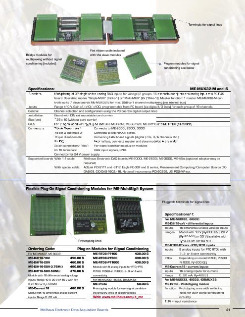
Terminals for signal lines<br />
Bridge modules for<br />
multiplexing without signal<br />
conditioning (included)<br />
Flat ribbon cable included<br />
with the slave modules<br />
Plug-on modules for signal<br />
conditioning see below<br />
Base Specifications: boards<br />
ME-MUX32-M and -S<br />
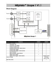
Functions<br />
Multiplexing of 32 single-ended analog DAQ inputs for voltage (2 groups, 16 channels each) into one analog input of a PC DAQ<br />
board. Operating modes “Single-MUX” (32-to-1) or “Multi-MUX” (2x [16-to-1]). Master function: 1 master ME-MUX32-M con-<br />
trolls up to 7 slave boards ME-MUX32-S for max. 256-to-1 channel multiplexing (via internal bus).<br />
Inputs<br />
Range ±10 V. Gain x1/x10/ x100, programmable from PC board (via digital I/O lines) for each group of 16 channels.<br />
Control<br />
Channel selection and confi guration using the PC board’s digital output lines<br />
Installation Board with DIN rail mountable card carrier<br />
Size (cm) ~25 x 10 (without card carrier)<br />
Sots<br />
For 2 signal conditioning plug-on modules ME-Proto, ME-Current, ME-Diff16 and ME-RTD8 (all models)<br />
Connectors 78-pin D-sub male 1: Connects to ME-2000i, 2600i, 3000.<br />
78-pin D-sub male 2:<br />
Connects to ME-FoXX® series.<br />
78-pin D-sub female:<br />
Remaining DAQ board signals (digital I/Os, D/A channels etc.).<br />
2x IDC:<br />
Internal bus, connects master and slave modules in any order.<br />
2x pin connectort/“slot”:<br />
For signal conditioning plug-on modules.<br />
2x 18 terminals:<br />
DAQ input signals, GND.<br />
Connector for 24 V power supply.<br />
Supported boards With 1:1 cable:<br />
Meilhaus Electronic DAQ boards ME-2000i, ME-2600i, ME-3000, ME-46xx (optional adaptor may be<br />
required)<br />
With special cable:<br />
ADLink PCI-9111 and -9112, Eagle PC-30F and G series, Measurement Computing/Computer Boards CIO-<br />
DAS-08, CIO-DAS-1602/16, National Instruments PCI-6025E, UEI PD2-MF-xxx.<br />
Flexible Plug-On Signal Conditioning Modules for ME-MultiSig® System<br />
Pluggable terminals for signal lines<br />
Ordering Code:<br />
For ME-MUX32, ME-SIG32:<br />
ME-Diff16-10V 450.00 $<br />
ME-Diff16-20V 460.00 $<br />
ME-Diff16-50V-3.75MΩ 460.00 $<br />
ME-Diff16-50V-50MΩ 470.00 $<br />
Module with 16 differential analog voltage<br />
inputs. Range 10 V, 20 V or 50 V with R i =<br />
3,75 MΩ or R i = 50 MΩ<br />
ME-Current16 460.00 $<br />
Modul with 16 differential analog current<br />
inputs. Range 0…20 mA<br />
Prototyping area<br />
Meilhaus Electronic Data Acquisition Boards<br />
Plug-on Modules for Signal Conditioning<br />
ME-RTD8-PT100 430.00 $<br />
ME-RTD8-PT500 430.00 $<br />
ME-RTD8-PT1000 430.00 $<br />
Module with 8 analog inputs for RTD/PTC<br />
Pt100, Pt500 or Pt1000. 2-, 3- or 4-wire<br />
connectivity.<br />
For ME-MUX32, -SIG32, -DEMUX32:<br />
ME-Proto 50.00 $<br />
Prototyping module for user signal conditioning<br />
circuitry. Area of soldering holes.<br />
Web: www.meilhaus.com/e_me<br />
Specifications 1) :<br />
For ME-MUX32, -SIG32:<br />
ME-Diff16-xxV - differential inputs<br />
Inputs 16 differential analog voltage inputs<br />
Ranges Model with 10 V (R i >200 GΩ), 20 V<br />
(R i >20 MΩ) or 50 V (available with<br />
R i =3.75 MΩ or 50 MΩ)<br />
ME-RTD8-PTxxxx - PTC/RTD inputs<br />
Inputs 8 analog inputs for PTC RTDs with<br />
2-, 3- or 4-wire connectivity.<br />
RTDs Depending on model Pt100, Pt500,<br />
Pt1000. R i >200 GΩ<br />
ME-Current16 - current inputs<br />
Inputs 16 analog inputs for current.<br />
Range 0…20 mA. R i =499 Ω<br />
For ME-MUX32, -SIG32, -DEMUX32:<br />
ME-Proto - Prototyping module<br />
Function Prototyping area with soldering<br />
holes for user signal conditioning<br />
circuitry.<br />
1) Ri = Input resistance<br />
41