ENVIRONMENTAL STATEMENT BARDOLINO DEVELOPMENT
ENVIRONMENTAL STATEMENT BARDOLINO DEVELOPMENT
ENVIRONMENTAL STATEMENT BARDOLINO DEVELOPMENT

Create successful ePaper yourself
Turn your PDF publications into a flip-book with our unique Google optimized e-Paper software.
Bardolino Development Environmental Statement<br />
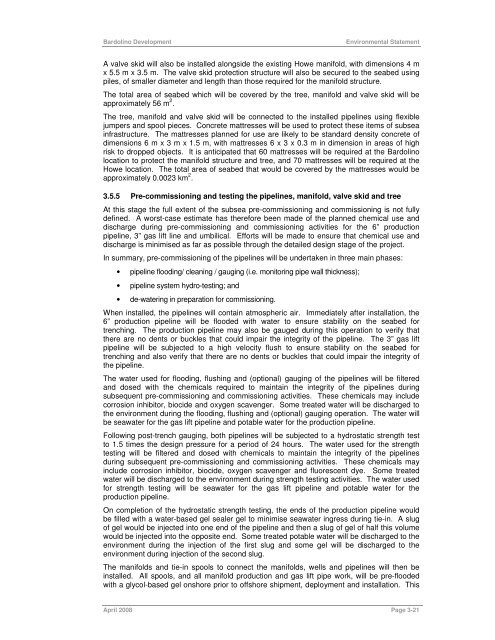
A valve skid will also be installed alongside the existing Howe manifold, with dimensions 4 m<br />
x 5.5 m x 3.5 m. The valve skid protection structure will also be secured to the seabed using<br />
piles, of smaller diameter and length than those required for the manifold structure.<br />
The total area of seabed which will be covered by the tree, manifold and valve skid will be<br />
approximately 56 m 2 .<br />
The tree, manifold and valve skid will be connected to the installed pipelines using flexible<br />
jumpers and spool pieces. Concrete mattresses will be used to protect these items of subsea<br />
infrastructure. The mattresses planned for use are likely to be standard density concrete of<br />
dimensions 6 m x 3 m x 1.5 m, with mattresses 6 x 3 x 0.3 m in dimension in areas of high<br />
risk to dropped objects. It is anticipated that 60 mattresses will be required at the Bardolino<br />
location to protect the manifold structure and tree, and 70 mattresses will be required at the<br />
Howe location. The total area of seabed that would be covered by the mattresses would be<br />
approximately 0.0023 km 2 .<br />
3.5.5 Pre-commissioning and testing the pipelines, manifold, valve skid and tree<br />
At this stage the full extent of the subsea pre-commissioning and commissioning is not fully<br />
defined. A worst-case estimate has therefore been made of the planned chemical use and<br />
discharge during pre-commissioning and commissioning activities for the 6” production<br />
pipeline, 3” gas lift line and umbilical. Efforts will be made to ensure that chemical use and<br />
discharge is minimised as far as possible through the detailed design stage of the project.<br />
In summary, pre-commissioning of the pipelines will be undertaken in three main phases:<br />
• pipeline flooding/ cleaning / gauging (i.e. monitoring pipe wall thickness);<br />
• pipeline system hydro-testing; and<br />
• de-watering in preparation for commissioning.<br />
When installed, the pipelines will contain atmospheric air. Immediately after installation, the<br />
6” production pipeline will be flooded with water to ensure stability on the seabed for<br />
trenching. The production pipeline may also be gauged during this operation to verify that<br />
there are no dents or buckles that could impair the integrity of the pipeline. The 3” gas lift<br />
pipeline will be subjected to a high velocity flush to ensure stability on the seabed for<br />
trenching and also verify that there are no dents or buckles that could impair the integrity of<br />
the pipeline.<br />
The water used for flooding, flushing and (optional) gauging of the pipelines will be filtered<br />
and dosed with the chemicals required to maintain the integrity of the pipelines during<br />
subsequent pre-commissioning and commissioning activities. These chemicals may include<br />
corrosion inhibitor, biocide and oxygen scavenger. Some treated water will be discharged to<br />
the environment during the flooding, flushing and (optional) gauging operation. The water will<br />
be seawater for the gas lift pipeline and potable water for the production pipeline.<br />
Following post-trench gauging, both pipelines will be subjected to a hydrostatic strength test<br />
to 1.5 times the design pressure for a period of 24 hours. The water used for the strength<br />
testing will be filtered and dosed with chemicals to maintain the integrity of the pipelines<br />
during subsequent pre-commissioning and commissioning activities. These chemicals may<br />
include corrosion inhibitor, biocide, oxygen scavenger and fluorescent dye. Some treated<br />
water will be discharged to the environment during strength testing activities. The water used<br />
for strength testing will be seawater for the gas lift pipeline and potable water for the<br />
production pipeline.<br />
On completion of the hydrostatic strength testing, the ends of the production pipeline would<br />
be filled with a water-based gel sealer gel to minimise seawater ingress during tie-in. A slug<br />
of gel would be injected into one end of the pipeline and then a slug of gel of half this volume<br />
would be injected into the opposite end. Some treated potable water will be discharged to the<br />
environment during the injection of the first slug and some gel will be discharged to the<br />
environment during injection of the second slug.<br />
The manifolds and tie-in spools to connect the manifolds, wells and pipelines will then be<br />
installed. All spools, and all manifold production and gas lift pipe work, will be pre-flooded<br />
with a glycol-based gel onshore prior to offshore shipment, deployment and installation. This<br />
April 2008 Page 3-21

![Download Shell AutoGas Stationen [Stand: Januar 2013] (PDF](https://img.yumpu.com/9982753/1/190x245/download-shell-autogas-stationen-stand-januar-2013-pdf.jpg?quality=85)